Calculation of the module of a cylindrical worm gear. Worm gears
The principle of operation and scope. Worm gear (figure 11.19) refers to gears with meshing shaft axes. The angle of intersection is usually 90 °. Movement in worm gears is converted according to the principle of a screw pair or the principle of an inclined plane. A worm gear consists of a screw, called a worm (Figure 11.20), and a gear, called a worm wheel (Figure 11.22). When the worm rotates around its axis, its turns move along the cylindrical surface forming it and the worm wheel rotates. The worm and worm wheel are made by cutting teeth with the help of a special tool from whole blanks. In the worm gear the same as in the gear, there are diameters of the dividing cylinders (Figure 11.19): d 1 - dividing diameter of the worm, d 2 - pitch diameter of the worm wheel. The point of tangency of the pitch diameters is called the engagement pole.
Figure 11.19 - Scheme of the worm gear.
Advantages of worm gears:
1. The possibility of obtaining a large gear ratio in one stage (i= 8 – 200).
2. Smooth and quiet operation.
3. Compactness (small size).
4. Braking (the inability to transfer torque from the worm wheel to the worm).
5. Damping properties reduce machine vibration.
The disadvantages of worm gears:
1. Considerable friction in the engagement zone.
2. Heat transfer.
3. Low efficiency.
Worm gears are used in devices with limited power (usually up to 50 kW).
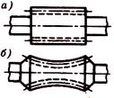
Figure 11.20 - Worms.
Worm gears are used in the mechanisms of dividing and feeding gear cutting machines, longitudinal milling machines, deep boring machines, lifting and traction winches, hoists, load lifting mechanisms, booms and turning automobile and railway cranes, excavators, elevators, trolley buses and other machines.
Worms. According to the shape of the surface on which the thread is cut, there are cylindrical (Figure 11.20, a) and globoid (Figure 11.20, b) worms. The shape of the thread profile is straight (Figure 11.21, a) and curved (Figure 11.21, b) with a profile in axial section. More commonly used cylindrical worms. In worms with a straight profile in the axial section in the end section, the coils are outlined by an Archimedean spiral, therefore the Archimedes are called a worm, which is similar to a trapezoidal screw.
Involute worms have an involute profile in the end section and are therefore similar to helical involute wheels, in which the number of teeth is equal to the number of visits of the worm. The main geometrical parameters of the worm are: = 20 ° is the profile angle (in axial section for archimedes worm and in the normal section of the tooth with cutting of an involute worm); r - the pitch of the teeth of the worm and the wheel corresponding to the pitch circles of the worm and the wheel; t =axial module; z 1. -the number of visits of the worm; - the diameter coefficient of the worm; - elevation angle of the helix ![]() ; d 1 =qm -pitch diameter (hereinafter see figure 11.21); d a 1 = d 1 + 2m- the diameter of the projections; d fl = d 1 - 2,4m - diameter of a circle of hollows; b 1 - the length of the cut part of the worm, it is determined by the condition of using simultaneous gearing of the largest number of teeth of the wheel [with z 1 = 1 ... 2 b 1\u003e (11 + 0.06z 2) m at z 1 = 4 b 1 ≥(12.5 + 0.09z 2) m].
; d 1 =qm -pitch diameter (hereinafter see figure 11.21); d a 1 = d 1 + 2m- the diameter of the projections; d fl = d 1 - 2,4m - diameter of a circle of hollows; b 1 - the length of the cut part of the worm, it is determined by the condition of using simultaneous gearing of the largest number of teeth of the wheel [with z 1 = 1 ... 2 b 1\u003e (11 + 0.06z 2) m at z 1 = 4 b 1 ≥(12.5 + 0.09z 2) m].

Figure 11.21 - The shape of the thread profile of the worm and the main geometric parameters
Meanings m and q standardized.
Worm wheels. When cutting without offset (figure 11.22):
d 2= z 2 m - the diameter of the pitch circle in the main section;
d a 2 = d 2 + 2m - the diameter of the projections in the main section;
d f 2 = d 2 - 2,4m - diameter of a circle of hollows in the main section;
a w= 0.5 (q + z 2) m - center distance.
In table 11.3 sizes b 2 -worm wheel width and d aM 2 - the largest wheel diameter corresponding to the angle of worm circumference by the wheel 2δ = 100 ° for power transmissions:
Table 11.3
Note.The number of teeth of the wheel from the condition of non-cutting accept:
Accuracy of manufacture. For worm gears, the standard provides twelve degrees of accuracy. For gears that require high kinematic accuracy, recommend III, IV, V and VI degrees of accuracy; for power transmissions recommend V, VI, VII, VIII and IX degrees of accuracy.
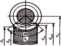
Figure 11.22 - The main geometrical parameters of the worm wheel
Gear ratio In the worm gear, in contrast to the gear, the peripheral speeds v 1and v 2do not match (see. Fig. 11.23). They are directed at an angle of 90 ° and are different in size, relative movement dividing cylinders do not run in like gear cylindrical and bevel gears, and slide. With one turn of the worm, the wheel will turn through an angle covering the number of teeth of the wheel, equal to the number of worm hits. The wheel will make a full turn at the speed of the worm, i.e.
Because z 1can be equal to 1, 2 or 4 (which can not be at the gear), then in one worm pair you can get a large gear ratio.
Slip in gearing. When moving, the turns of the worm slide along the teeth of the wheel, as in a screw pair. Sliding speed v sdirected tangentially to the worm helix. As a relative speed, it is equal to the geometric difference between the absolute speeds of the worm and the wheels, which are the peripheral speeds v land v 2(see fig. 11.19 and fig. 11.23); or, while
![]()
![]()

Fig. 11.23. The scheme for determining the sliding speed
where is the elevation angle of the worm helix. Because< 30°, то в червячной передаче v 2less v 1a v smore Large slip in worm gears causes lower efficiency, increased wear and a tendency to seize.
Worm gear efficiency determined by the formula (11.48). The difference is only in the definition of losses in the mesh. By analogy with the screw pair KP.D. gearing with a leading worm is determined by the formula:
Efficiency increases with an increase in the number of visits of a worm (increases) and with a decrease in the coefficient of friction or angle of friction f. If the wheel is leading, then the direction of the forces changes and then we get
When ≤, 3 = 0, the transfer of movement in the opposite direction (from the wheel to the worm) is impossible. We get a self-braking worm pair.
It was established experimentally that the coefficient of friction depends on the sliding speed. With increasing v sgoing down. This is due to the fact that v sleads to a transition from semi-fluid friction to liquid friction. The values of the friction coefficient also depend on the roughness of the friction surfaces and the quality of the lubricant.
For preliminary calculations, when and v snot known, efficiency can be selected by the average values from table 11.4.
Table 11.4
After determining the size of the transfer efficiency is specified by calculation.
Forces in gearing. In the worm gearing (see. Fig. 11.24) act: the circumferential force of the worm F t 1equal to the axial force of the worm F a 2,
wheel circumference F t 2 equal to the axial force of the worm F a 1
radial force
(11.71)
normal strength
![]() (11.72)
(11.72)
In the axial plane of force F tzand F rare constituents F n = F n cos(projection of normal force on the axial plane). T 1 -moment on the worm, T 2- the moment on the wheel:
T 2 = T(11.73)
Basic performance criteria and calculation. Worm gears are calculated from bending stresses and contact stresses. There is more wear and jams. This is due to the high sliding speeds and the unfavorable direction of sliding relative to the contact line. To prevent seizure, special anti-friction materials are used: a worm - steel, a wheel - bronze or cast iron.

Fig. 11.24. Worm gearing forces
The intensity of wear depends on the contact stresses. The main calculation is carried out by contact stresses. The calculation of the bending stresses is performed as a test.
Calculation of contact stresses. The equation
 (11.74)
used for the calculation of worm gears. For Archimedean worms, the radius of curvature of the turns of the worm in the axial section is ρ 1 =. Then by the formula (11.8) taking into account equation (11.20) we get
By analogy with the helical gear, the worm gear unit load
where is the total length of the contact line (see fig. 11.22); α = 1,8 ... 2,2 - face coefficient of overlap in the median plane of the worm wheel; ≈ 0.75 is the coefficient taking into account the reduction in the length of the contact line due to the fact that contact is not ensured along the full arc of the circumference 2δ. After substitution in the formula (11.74) we get
DISADVANTAGES, CLASSIFICATION, MATERIALS OF WHEELS
WORM TRANSFERS: FEATURES OF THE DESIGN, ADVANTAGES AND
A worm gear consists of a screw, called a worm, and a worm wheel, which is a type of helical gear. The axes of the transmission shafts intersect, the angle of intersection is usually 90 0.
Picture 1
In contrast to the helical wheel, the worm wheel rim has a concave shape, which contributes to a certain fit of the worm and, accordingly, an increase in the length of the contact line. The thread of the worm can be single or multiple (2, 4).
Advantages:
The possibility of obtaining a large gear ratio;
Smooth and quiet operation;
The possibility of obtaining self-braking (when changing the input).
Disadvantages:
Relatively low efficiency (with a single-threaded worm - 0.72; with a two-threaded - 0.8, with a four-threaded - 0.9);
The need to use expensive anti-friction materials for the wheel;
Increased wear and heat.
Worm gears are classified according to various criteria:
1) in the form of a worm:
With a cylindrical worm (Figure 2a);
With globoid worm (Figure 2b);
B) with globoid worm
Figure 2
2) the shape of the profile of the worm coil:
With Archimedean worm (according to GOST 19036-81 denoted -ZA). In the axial section, the tooth profile has the shape of a trapezium, in the end section - the shape of an Archimedean spiral (Figure 3a);
With a convolute worm having straight-line outlines of a coil in a normal section (Figure 3b);
An involute worm (ZJ), representing a helical gear with a small number of teeth and with a large angle of inclination (in the face section, the tooth has an involute profile (Figure 3c).
Figure 3
Due to the high sliding speeds, worm pair materials must have anti-friction properties, wear resistance and low tendency to jam.
Worms are made from carbon or alloyed steels. Couples in which the turns of the worm are heat-treated to high hardness with subsequent grinding have the highest loading capacity.
Worm wheels are made mostly of bronze, less often of cast iron.
Tin bronze such as OF10-1, ONF are considered the best material, but they are expensive and scarce. Apply at high speeds V s = 5 ... 25 m / s. Non-tin bronze, for example aluminum-ferruginous type Br.AZh9-4, have enhanced mechanical characteristics, but have reduced anti-seize properties. They are used for V s<5m/c. Чугун применяют при V s <2м/с, преимущественно в ручных приводах.
In worm gears, the standard profile angle is assumed to be 20 °: for Archimedean worms in axial section, for convolute ones - in the normal section, for involute ones - in a normal section of a helical joint that engages with the worm. The distance between the like points of the respective lateral sides of two adjacent turns of the worm, measured parallel to the axis, is called the calculated step and denoted P. The ratio P / π is called the module. The module (m) is a standard parameter: for a worm, it is axial, for a worm wheel - front-face.
Consisting of two moving links - a worm and a gear and designed to transmit and convert the rotational motion between orthogonal intersecting axes. Worm is called a link, the outer surface of which has the shape of a screw. A worm wheel is a gear wheel with oblique teeth, which engages with a worm.
Types of worm gears and worms (according to GOST 18498-73):
1. by the appearance of the dividing surface of the worm
Cylindrical worm gears - the worm and the wheel in the gear have cylindrical pitch and initial surfaces;
Globoid worm gears - the separator and the initial surface of the worm are formed by rotating the segment of the arc of the separating or initial surface of the twin worm wheel around the axis of the worm;
2. by the appearance of a theoretical face profile of a worm coil
Archimedes worm (ZA) - the profile is made along the Archimedean spiral;
Involute worm (ZI) - the profile is made on an involute of a circle;
Convolute worm (ZN) - the profile is made along an elongated involute.
(fig. 14.4)
Gearing geometry of a cylindrical worm gear:
The calculation of the gearing geometry of a cylindrical worm gear is governed by GOST 19650 - 74. The relationship between the main parameters of the worm - the diameter of the initial cylinder d w1, the course of the helix pz1 and its angle of inclination bw - is established by the following relation
(fig. 14.5)
![]()
The relationship between the course of the helix pz1 and pitch multiple screw p1
![]()
Gearing geometry calculation:
Initial data
m - axial module;
q - the diameter coefficient of the worm;
z1 - the number of turns of the worm;
aw - center distance;
x - the coefficient of displacement of the worm;
u- gear ratio.
Tool parameters
h * = (h * w + c * 1) - the height ratio of the coil;
h * a - head height ratio;
s * - coefficient of design thickness;
r * f - coefficient of radius of curvature of the transition curve;
c * 1,2 = 0.25 ... 0.5 ; s * = 0.75 h p ; r * f = 0.3 ... 0.45
(fig. 14.6)

Calculation of geometric parameters:
1. Wheel teeth number
2. Offset factor (if center distance is set)
* Center distance (if offset factor is specified)
3. Pitch diameters
![]()
4. Starting diameters
![]()
5. Pitch angle worm coil
![]()
6. Starting angle worm coil
7. Main angle of ascent worm coil (only for ZI worms)
and the main diameter of the worm
![]()
8. Height worm coil
9. Head height worm coil
10. Vertex diameters
turns of a worm
the teeth of the worm wheel in the middle face plane
11. Trough diameters
worm wheel
12. Largest diameter worm wheel
13. Crown width worm wheel
14. Cut length worm (with x = 0)
Geometric quality indicators of gearing:
1. Trimming the worm wheel teeth is missing if
(at small elevation angles, the transfer of movement from the worm wheel shaft to the worm becomes impossible)
disadvantages :
high sliding speed along the tooth line, which leads to an increased tendency to seize (special lubricants and materials are needed for the worm gear ring gear), lower efficiency and higher heat dissipation.
Worm gears - a kinetic pair, designed to transfer torque. It consists of a worm and a wheel.
Mandatory condition - the shafts between them form a right angle. It has the following advantages:
- increased gear ratios (up to 300 and higher);
- smooth contact and noiselessness;
- transmitted power reaches 60 kW.
The minus of the kinetic pair is that the part has a rather low efficiency (0.7-0.92), and with strong heating and long-term operation it can quickly fail. At the same time, the cost of bronze, from which the wheel is made, is quite high.
Our company makes transfers according to drawings and finished samples in small and large batches.