Check and adjust gearing gears gears
To ensure the correct operation of the bevel gears of the main gear, it is necessary that the axial movement of the gears when transmitting torque through them is minimal, therefore, the preload of tapered bearings is preloaded. As the transmitted torque increases, the tightness of the tapered bearings decreases, but at torque values close to the maximum, gears get the minimum axial displacement, resulting in a decrease in their wear.
However, excessive preload can dramatically reduce bearing life.
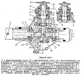
Fig. Driving mechanism drive driven axle
The correctness of the bearing adjustment is determined by the amount of torque that must be applied to the shafts mounted on the bearings in order to turn them. The moment is measured by a torque tool. The preload of the tapered bearings 16 of the main drive shaft is adjusted by varying the thickness of the washers between the inner rings of the bearings. In this case, the inner rings move axially relative to the outer rings of the bearings, and the distance between the conical surface of the inner ring and the conical surface of the outer ring of each of the bearings changes; The degree of clamping of the tapered rollers between the rings also changes. Similarly, roller tapered bearings of the driven bevel gear 13 are adjusted. Adjustment of the roller tapered bearings of the differential housing is made by turning the adjusting nuts, which provides axial movement of the outer rings of the bearings relative to the inner ones.
After adjustment, the preload of the roller tapered bearings regulate the bevel gear engagement by the tooth contact spot, for which a thin layer of paint is applied to the teeth of the leading bevel gear and then the gears are turned. With proper gearing of the gears, the contact patch at the driven bevel gear is about 2/3 of the tooth's length and shifts slightly to its narrow part, being located in the middle of the height of the tooth.
Depending on the location of the contact patch, adjust the position of the gears in accordance with the instructions of the factory instructions.
The position of the drive bevel gear 14 is controlled by changing the number of shims between the bearing housing 16 and the flange of the main gear case 18, and the position of the driven bevel gear 13 with the help of the spacers between the two-row tapered roller bearing body and the side flange of the main gear housing 18. Achieving the required position of the contact patch on the teeth of the driven bevel gear, control the side clearance between the teeth of the driving and driven bevel gears, which averages 0.15 ... 0.3 mm.
The adjustment of the gearing of the bevel gear pair is made by longitudinal movement of the cups 5, 10, 25, which is carried out by changing the thickness of the gaskets 6, 14 and turning the round nuts.
The adjustment of the gearing of the bevel gears is made by moving them along their axes with the subsequent fixation of the wheels in the required position.
Adjustment of gearing gears can be made by shifting the gasket from under one crankcase cover under the other. With proper adjustment of the gearing, the movement of the flange of the shank around the circumference of a radius of 40 mm should be between 0 2 - 0 6 mm.
It is not recommended to adjust the gearing of gears to reduce the lateral clearance between the teeth when they are worn, as this will cause a violation of the relative position of the running-in surfaces of the teeth and may cause their breakdown. When replacing worn gears with new ones, it is necessary to adjust their mutual position with the help of shims. In this case, you must first adjust the bearings.
Adjustment of gearing gears during assembly at the factory do not produce, as the correct gearing gears provided the appropriate tolerances on the mating parts. When overhauling to compensate for the wear of the bearings, check the correctness of the gearing clutch on the paint. The adjustment is made by removing part of the gaskets from under the flange of the bearing housing of the drive pinion shaft. The lateral clearance between aubyami should be within 0 1 - 0 4 mm, which corresponds to the angular displacement of the cardan flange on the radius of the holes by 0 25 - 0 9 mm. The standard package includes gaskets with a thickness of 0 100 - 0 085; 0 25 - 0 23 and 0 80 - 0 75 mm.
The gearing of the bevel gears of the main gear is adjusted by axial movements of their shafts. Small bevel gear move, changing the number of adjusting shims installed between the shaft housing of a small bevel gear and crankcase main gear. The standard package includes gaskets with a thickness of 0 05; 0 1; 0 2; 0 5; 1 0 mm. Gaskets 0 1 and 0 5 mm set on demand.
The gearing of the bevel gears of the main gear is adjusted by axial movements of their shafts. Small bevel gear move, changing the number of adjusting shims installed between the shaft housing of a small bevel gear and crankcase main gear.
Adjusting the gear on the paint according to the nature of the contact patch is made as follows.
Adjusting the gear on the paint according to the nature of the contact patch is made as follows. The teeth of one wheel are smeared with paint and both wheels, after their adhesion, are checked for two or three turns. As a result, imprints appear on the teeth of the wheel, not smeared with paint, by which the quality of the gearing is judged. As already noted, the most favorable imprint is considered, when wheels without a load transfer efforts by a thin part of the tooth (see FIG.
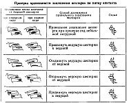
| Control circuit assembly assembly bevel gears. | Types of paint prints with incorrectly meshed spur bevel gears. |
Adjusting the engagement according to the nature of the contact patch is made as follows.
Adjustment of the gearing of the bevel gears of the main gear is carried out after installing the driven gear in the crankcase and checking the bearings. Installation of the driven bevel gears produced depending on the design of the rear axle. Before installing it from the car M-20 pre-assemble the crankcase cover and axle shrouds with bearings and seals. The outer rings of tapered roller bearings are installed in the holes of the crankcase cover until it stops at the end. Two glands are pressed into the casing of the axle shaft, their working surface is greased with grease.
Normal engagement of bevel gears protects them from premature wear and breakage and reduces friction in the teeth. Such an engagement of bevel gears is correct when their axes lie in the same plane, perpendicularly to one another, and the tops of the cones coincide. To do this, bevel gears must be installed in a certain position in the rear axle housing.
As a result of the wear and tear of parts, the gear engagement may be broken. With significant wear of bearings and their mounting seats, the perpendicularity of the axles of the gears is broken or the axles may not be in the same plane; when the teeth wear out, the side clearance between the gears increases and the contact surface shifts along the height of the tooth.
In the first case, it is necessary to replace the bearings. To restore the original position of the gears by moving them in the axial direction. Compensation of wear of gear teeth by their additional movement is not allowed, since when a normal clearance is established between worn teeth, the tips of the cones will not coincide.
When assembling the rear axle, the pinion gear 28 (see the diagram of the rear axle of the “Belarus” tractor) is set so that the distance between its rear end and the geometrical axis of the differential is 130 ± 0\u003e 15 mm. This is achieved by laying under the flange of the glass of the front bearing of the primary shaft of the gearbox. The side clearance in the gear teeth in the range of 0.25 - 0.50 mm is regulated by gaskets 22 under the flanges of the right and left glasses of the bearings of the differential axis. The correctness of gearing gears check for paint: the teeth of the pinion gear cover with a thin layer of paint and turn the driven gear one turn.
An engagement is considered correct if the ink imprint is located not less than 80% of the length of the tooth of the driven gear and the middle of the imprint does not have a large displacement towards the base or the top of the tooth.
The amount of lateral clearance is determined by a lead plate rolled between the teeth at the large gear base, or by an indicator.
The correctness of the gearing and the amount of lateral clearance of the gears that are in operation are checked during routine repairs of the tractor or when signs of abnormal operation of the bevel gear occur. In the latter case, it is necessary to check if there are no chips, nicks and other malfunctions on the gears, whether the crown of the driven gear on the hub or the left bearing on the differential axis has weakened.
To adjust the gearing of the working gears should be only in the case when the rear axle disassembled or if the gap in the teeth exceeds 1.2 mm. The order of such adjustment is as follows: disconnect the brake rod and remove the lids of the cups; screwing the two bolts into the mounting holes of the flange, press out the right cup so that you can remove the gaskets 22; in the same way, press out the left cup by the size of the gap between the gear teeth; Using the gaskets, install an increased clearance taking into account the wear of the teeth and check the correctness of the gearing gear alignment by the nature of the print; after that, fill the bearings of the differential axle with grease and put the lids of the cups so that the grooves in them coincide with the oil supply holes in the cups.
The bearings, side clearance and contact in meshing gears of the main gear of the UAZ-452 are initially adjusted at the factory. During operation, as a rule, they do not need to be adjusted. Adjusting them is necessary only when replacing any parts, bearings, or when the axial clearance in the bearings.
Increased lateral clearance between the gear teeth of the main gear, which appeared due to their wear, cannot be reduced by adjustment, since in this case the relative position of the running gears will be disturbed, which will lead to an increase in noise, possibly also breaking the teeth.
The axial clearance in tapered roller bearings, which appeared during operation, should be eliminated without disturbing the position of running gears of the main gear. Lateral clearance and gearing in the teeth of the main gears regulate only when they are replaced.
When the axle clearance of the driven gear appears, it is checked through the oil filler hole at the remote axles, it is necessary to add shims of the same thickness to the right and left sides of the satellite box, while ensuring that the driven gear is turned with a small effort.
Differential bearings after parts replacement are adjusted as follows:
1. Press the inner rings of the differential bearings onto the journals of the differential box so that there is a gap between their ends and the ends of the satellite box within 3.0-3.5 mm.
2. Install the differential assembly in the crankcase, put the gasket in the crankcase connector to take into account its thickness when adjusting, and then install the cover, and carefully turning it in both directions, roll the bearings so that the rollers take the correct position. Housings axes in this case should be in a vertical position. Then, without disturbing the rolling of bearings, evenly connect the cover with the crankcase with bolts and nuts.
3. Unscrew the nuts and bolts and remove the cover. Carefully remove the differential from the crankcase and accurately measure the dimensions A and A1 between the ends of the satellite box and the inner bearing rings using a feeler gauge.
4. To choose a package of gaskets with a thickness equal to the sum of the measured dimensions A + A1. To provide preload in the differential bearings to these gaskets add another gasket with a thickness of 0.2 mm. Thus, the total thickness of the selected package of shims must finally be equal to A + A1 + 0.2 mm.
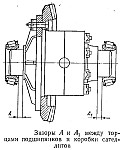
5. Remove the inner rings of the differential bearings from the necks of the satellite box. Divide the selected package of gaskets approximately in half. On the crankcase side, the thickness of the gaskets should be 0.3-0.4 mm greater than the thickness of the gaskets on the side of the cover. This is necessary in order to further prevent lateral engagement when adjusting the side clearance in the teeth of the driving and driven gears.
6. Install the gaskets on the neck of the satellite box and press the inner bearing rings onto them until they stop at the ends of the box.
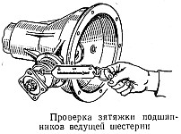
Axial movement of the pinion gear is not allowed. The axial clearance in the double tapered bearing and the weakening of its tightening violates the correct engagement of the teeth of the gears of the main gear, causes the inner ring to turn from the gland side, resulting in wear of the flange face, the ends of the oil ring, the spacer ring and the destruction of the shims. All this causes premature wear of the teeth of gears and the destruction of the bearings of the pinion gear.
Adjustment of the double tapered bearing is checked by rocking the flange by hand. If you feel the pitching of the pinion in the bearing, you should tighten the nut. If the nut is tightened to the full, and the axial movement is not eliminated, then by reducing the thickness of the package of shims and tightening the nut to failure, adjust the double tapered bearing, providing it with preload, the value of which is checked with a spring dynamometer.
At the same time it is necessary to remove the cover of the crankcase to remove the differential from the driven gear assembly. When properly adjusted, the spring dynamometer should show a force of 1.5–3 kgf when turning the gear for the hole in the flange. In the process of tightening the nut to failure it is necessary to produce a rolling of the bearing so that the rollers take the correct position.
After the pinion and differential bearings are adjusted, proceed to adjusting the side clearance and gearing of the teeth of the main gears. When adjusting the side clearance and the position of the gears of the main gear under the tapered bearing pinion set the adjusting ring. The thickness of this ring should be equal to 1.43 mm.
Adjusted double tapered bearing with drive gear assembly is pressed into the crankcase to the stop. In order to avoid damage to the raceway and rollers, the pressing force must be transmitted through its outer ring. Then install the oil ring and the cover of the double tapered bearing, which is slightly evenly fastened with bolts so as not to cause its deformation.
After installing the flange and washers, they tighten the nut and roll in the rollers, turning the flange. In the crankcase set the differential assembly with the driven gear. Having installed in the plane of the crankcase connector a gasket with which the differential bearings were adjusted, connect the cover to the crankcase with bolts and nuts. When such a pre-assembly is made, check the side clearance in engagement at four points through each revolution of the pinion gear.
To do this, with the help of semi-axles, the driven gear needs to be slowed down, and the drive gear should be turned in both directions until the teeth touch. The side gap between the teeth of the new gears of the main gear should be in the range of 0.1-0.3 mm. This gap corresponds to a value of 0.2-0.6 mm, measured with the angular movement of the flange along the arc of the hole radius.

Side clearance regulate the permutation of gaskets from one side of the satellite box to the other. If you remove the gasket from the side of the cover, the gap in the mesh increases, but if you add - the gap decreases. Gaskets can only be rearranged from one side to the other, but they can neither be reduced nor added, as this will break the adjusted preload of the differential bearings.
After adjusting the side clearance, the gearing of the main gears is checked. To do this, paint the paint of a certain consistency on the teeth of the driven gear. Liquid paint spreads and stains the surface of the teeth, making it difficult to determine the actual location of the contact patch, too thick paint is not squeezed out of the gaps between the teeth.
With the help of semi-axes, it is necessary to slow down the driven gear, and drive the leading one in both directions until a clear contact patch is indicated. Upon receipt of the correct stain contact of the teeth, check the installation of gears and side clearance meshes ends. The following are typical contact patches on the teeth of the driven gears of the rear axle's main gear and ways to achieve proper gearing of the gears by moving the driving and driven gears.
Checking the correctness of the gears of the main gears of the rear axle of the UAZ-452 on the contact patch.
Moving the drive gear can be achieved by changing the thickness of the adjusting ring to move the drive gear away from the driven one, the adjusting ring needs to be set to a greater thickness, and vice versa, to move the driving gear to the driven one, the adjusting ring needs to be set smaller.
The movement of the driven gear is ensured in the same way as when adjusting the side clearance - by shifting the bearing spacers of the differential. After the adjustment is completed, its final assembly.
Mechanical transmission, working on the principle of engagement, can be toothed and worm.
Gears, in turn, are divided into cylindrical and conical. But this is not the last classification of gears.
Depending on the location of the teeth relative to the axis of the cylindrical wheels there are:
- cylindrical spur gears, the simplest in design and, accordingly, in manufacturing, they do not create axial loads on the shafts, therefore, do not need special thrust bearings, which greatly simplifies assembly. Such gears are used in mechanisms with a small working speed of rotation of the shaft. The disadvantage of spur gears is a lot of noise during the operation of the mechanism, especially if the transmission wheels are not accurately processed;
- cylindrical helical gears, their teeth are located along the helical lines on the separating cylinder. Since the teeth of such gears engage smoothly, gradually, the noise level decreases and the load capacity increases. However, due to the inclined arrangement of the teeth, the axial force tends to move the wheel with the shaft along the axis, therefore, when assembling helical gears, axial fixation of the shaft is required;
- cylindrical chevron gear is a wheel, the crown of which consists of alternating sections of the left and right teeth. With such an arrangement, the axial force is absent, which ensures the transfer of very large powers;
- cylindrical transmission internal gearing. The surfaces of the gears of this gear are located one inside the other, and the wheels rotate in one direction.
Before installing the wheels of cylindrical gears check their beating, that is, the concentricity of the profile of the teeth relative to the bore diameter. To do this, the gear wheel is mounted on a rigidly mounted mandrel, between the teeth set a cylindrical caliber, on which is placed the indicator leg, and record its readings. Turn the mandrel, shift the gauge through two or three teeth and re-record the readings, continue in this way until the full rotation of the mandrel, then from all readings choose the largest and smallest. If the received deviations do not exceed the allowed (according to the technical data for a particular mechanism), then the wheel is allowed to be assembled.
The assembly of spur gears consists of the following technological operations:
- preparation and verification of the collected units. Gear rings gears should be processed, checked for beating, washed, dried, they should not be defects in the form of nicks, burrs, burrs;
- assembly of gear wheels, of course, if the wheels are collapsible. They usually consist of a hub, which is made of steel or cast iron, and a crown of teeth (high-grade steel or textolite). The crown is pressed onto the disk of the hub and fixed either by welding or with the help of stoppers, which are screwed into specially drilled holes with a thread on the crown and disk of the hub;
- installation and fastening of gear wheels on shafts. Gears are put on the shaft, and their position is fixed with keys, splines or bolts;
- installation of shafts with gear wheels in housing bearings;
- adjustment of teeth engagement in a separate pair of wheels and in the transmission as a whole. To adjust check the quality of gearing on the paint. The teeth of a smaller wheel diameter are covered with a thin layer of paint and scroll a couple of gears one turn and back. With proper hooking, the paint spots on the twin wheel should be located on the middle part of the side surface of the teeth and occupy at least 50–60% of the tooth surface in height and at least 70–90% in length. If the spots are displaced along the length of the surface, then the axes of the shafts are skewed. The displacement of spots in height closer to the tooth stalk indicates a decrease in the center-to-center distance of the shafts, and closer to the head of the teeth, an increase in the center-to-center distance.
Bevel gears are an integral part of gears in which the axes of the shafts intersect at a certain angle (the most common are 90 °). The shape of the teeth of the bevel gears can be straight, oblique and round. Wheels with oblique and round teeth are used in gears experiencing heavy loads and high shaft speeds (for example, when transmitting rotation from the gearbox to the rear axle of a car).
The techniques for installing and securing wheels in bevel gears are similar to those for installing and securing cylindrical gears. But when assembling bevel gears, it should be remembered that the gearing of the wheels is correct when both wheels are set in such a way that the constituents of the initial cones (I – I and II – II) match, and the estimated centers of the cones (O and O1) coincide ( Fig. 63).
Fig. 63. Bevel gear.
Before installing shafts with conical wheels, check the correctness of the relative position of the axes of their seats, for which two mandrels that are centered in the holes are installed on the seats: if the probe enters the gap between them freely, the arrangement of the axes is correct.
Normal operation of the bevel gear is possible only if there is a lateral gap between the teeth of the mating wheels.
The size of the gap is different for each type of mechanism and is in the range of 0.08–0.20 mm. Measure the amount of side clearance can probe, if the wheels have free access. But control with the help of lead plates is more common: a lead plate is passed between the teeth of the mating wheels and the wheels are turned. Repeat the operation in several places evenly spaced around the circumference, each time using a new plate.
A micrometer (see Fig. 1, b) measures the thickness of each of the deformed plates; the size of the gap is defined as the arithmetic average of the obtained measurements.
If the actual clearance does not correspond to the required value, its size is adjusted, for which one of the wheels is moved either towards the intended apex of the cone to reduce the clearance, or from it to increase it. And in order to fix the new position of the tapered wheels, gaskets are installed under their bearing surfaces.
The assembled toothed bevel gear is checked for the quality of the gearing (checking for paint is similar to checking for cylindrical gears), for the noise level (at its high transmission level they are burned out in slow mode), for friction (if the lubricant does not overheat, then friction in the interfaces is normal).
Worm gears are used if the geometric axes of the shafts intersect with each other, usually at an angle of 90 °.
The worm gear consists of a worm and a worm wheel. At the same time, the worm can be straight - cylindrical (1-2 teeth of a worm wheel simultaneously engage with it) - or globoid - concave (5-6 teeth are simultaneously engaged here, as a result of which they are significantly ahead of cylindrical worm gears and efficiency). When assembling the worm gears, first of all, the bearings are installed in the mechanism housing, and already in them - the shafts on which the worm and the worm wheel are mounted.
Before the final fastening of the gear unit, check the correctness of the teeth hooking on the paint: in this case, cover the screw surface of the worm with a thin layer of paint, then turn it slowly (Fig. 64).
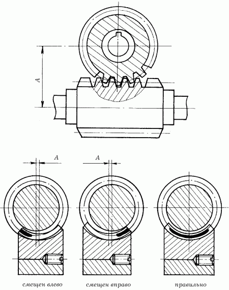
Fig. 64. Control of correctness of the gearing of the worm gear.
With proper engagement, the paint should cover the side surface of the worm wheel teeth in the length and height of at least 50–60% (in the middle part).
You can adjust the gearing of the worm gear by selecting the appropriate thickness of the right or left gasket under the worm wheel flange (for convenience, they are made in the shape of half-rings, so installing them does not require disassembling the assembly, just loosen the set screws). In many gears of this type, the bearing cups in which the worms are mounted are threaded, so the gearing adjustment can be done by turning the nuts, moving them along with the gear wheels along the axis.
From the book: Korshever N. G. Works on metal