Designation of asterisks for chains. Chain sprockets
STATE STANDARD OF THE UNION SSR
UNIFORM SYSTEM DESIGN DOCUMENTATION
RULES FOR IMPLEMENTATION OF DRAWINGS OF DIFFERENT PRODUCTS
RULES FOR IMPLEMENTATION OF WORK DRAWINGS
STARS DRIVE ROLLER
And SLEEVE CHAINS
GOST 2.408-68
MOSCOW - 1998
STATE STANDARD OF THE UNION SSR
|
Unified system for design documentation RULES FOR IMPLEMENTATION OF WORK DRAWINGS Unified system for design documentation. |
Introduction date 01.01.71
1. This standard establishes the rules for the implementation of gearing elements on working drawings of sprockets for driving roller and sleeve chains with a tooth profile according to GOST 591 .2. Working drawings of sprockets for driving roller and sleeve chains should be made in accordance with the requirements of the standards of the Unified system for design documentation and this standard. 3. On the image of an asterisk (Fig. 1 - 3) indicate: the width of the tooth of the asterisk, the width of the crown (for multi-row asterisk); the radius of curvature of the tooth (in the axial plane); the distance from the top of the tooth to the line of the centers of arcs of curvature (in the axial plane); rim diameter (largest); radius of curvature at the border of the rim (if necessary); diameter of projections; surface roughness of the profile of the teeth, end surfaces of the teeth, surface of the projections and roughness of the surface of the teeth rounding (in the axial plane). 4. In the drawing, an asterisk in the upper right corner is placed a parameter table. The dimensions of the graph of the table, as well as the dimensions that determine the location of the table in the drawing field, are shown in fig. one . 5. The table of parameters of the spider gear consists of three parts, which are separated from each other by solid main lines: the first part is the basic data (for manufacturing), the second part is the data for control, the third part is the reference data (see drawing 1 - 3). 6. In the first part of the parameter table, the number of sprocket teeth z; parameters of the mating chain: step t and diameter of the roller d 3 or sleeve d 2; tooth profile according to GOST 591 with the inscription: “With offset” or “Without offset” ); accuracy group according to GOST 591.7. In the second part of the table of parameters, the following is given: the size of the diameter of the cavities D i and the maximum deviations (for sprockets with an even number of teeth) or the size of the largest chord L x and the maximum deviations (for asterisks with an odd number of teeth); the tolerance for the difference of the steps; the radial beating tolerance the circumference of the depressions; the tolerance of the face runout of the ring gear. In the third part of the parameter table, the following factors are given: pitch diameter d d; width of the internal plate of the chain h; distance between the internal plates of the chain b 3; for a multi-row chain, the distance between the rows of chain A; number of rows of the chain. to the elements of the hooking.6 - 8. (Modified edition, Change No. 2). 9. If the sprocket consists of several gear rims, different in the number of teeth or in the number of teeth and chain pitch, the parameter values are indicated in the parameter table for each rim in separate graphs. Each ring gear and the corresponding column (column) of the table are designated by capital letters of the Russian alphabet (see Fig. 3) .10. Unused columns of the table of parameters exclude or cross out. 11. Examples of the implementation of the engagement elements in the working drawings of the asterisks are shown in fig. 13 .
An example of the gear ring of the sprocket for a single-row drive roller normal chain
* Size for reference.
An example of the drawing of the gear teeth of the sprocket for the drive roller three-row chain
* Size for reference.
An example of the drawing of the gears of the sprocket for single-row chains
* Size for reference.
(Modified edition, Amendment No. 2).
INFORMATION DATA
1. DEVELOPED AND INTRODUCED by the Committee of Standards, Measures and Measuring Instruments under the Council of Ministers of the USSR. Verchenko, Ya.G. Old resident, Yu.I. Stepanov, V.I. Dozortsev2. APPROVED AND INTRODUCED BY Resolution of the Committee of Standards, Measures and Measuring Instruments under the Council of Ministers of the USSR of June 19, 1986 No. 948Amendment No. 2 was adopted by the Interstate Council for Standardization, Metrology and Certification (Minutes No. 8 of October 12, 95). changes voted:
|
State name |
Name of national standardization body |
| Republic of Belarus | State Standard of Belarus |
| The Republic of Kazakhstan | Gosstandart of the Republic of Kazakhstan |
| The Republic of Moldova | Moldovstandart |
| Russian Federation | State Standard of Russia |
| The Republic of Tajikistan | Tajik Standard |
| Turkmenistan | Main State Inspectorate of Turkmenistan |
| Ukraine | State Standard of Ukraine |
Dimensions of star gears (according to GOST 591-69) for roller and sleeve chains are shown in fig. 7 and 8.
Note: The dimensions below are necessary for producing drawings for chain-sprockets. To perform the drive assembly drawing, it is sufficient to calculate the pitch diameter, the diameter of the protrusion  and sizes shown in fig. eight.
Initial data: chain pitch t, number of sprocket teeth zthe diameter of the gearing element d 1 (according to table 1 of the annex)
Pitch diameter  .
.
The diameter of the circumference of the projections.
The radius of the cavities.
The diameter of the circumference of the hollows  .
.
Pairing radius.
The radius of the tooth head.
Half the corner of the depression  .
.
Mate angle  .
.
Half angle tooth  .
.
Offset of arc centers of hollows  .
.
Note: If the chain sprocket is performed without shifting the centers of the arcs of the valleys,  .
.
Straight section of the profile.
The distance from the center of the arc of the depression to the center of the arc of the protrusion of the tooth  .
.
Point coordinates  :
: ;
; .
.
Point coordinates  :
: ;
; .
.
The radius of curvature of the tooth is the smallest  .
.
The distance from the top of the tooth to the center line of the arcs of rounding  .
.
The diameter of the groove.
Radius of curvature  = 1.6 mm with chain pitch
  up to 35 mm;
= 2.5 mm with chain pitch over 35 mm.
The width of the tooth for a single chain.
The width of the tooth for the two- and three-row chain.
Width for double and triple chain  .
.
The diameter of the circumference of the protrusions  calculated with an accuracy of 0.1 mm; other linear dimensions - up to 0.01 mm, and angular - up to 1 до.
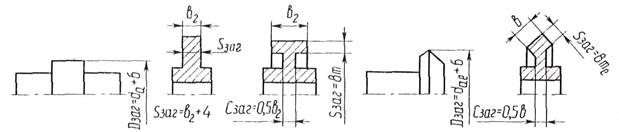
3.2 Design of the hub and disc chain sprockets
The design of a nave and a disk of asterisks of chain transfers is presented on fig. 9.
|
|
|
Fig. 9. The design of the chain sprocket. |

The value of the diameter of the shaft is taken from the design of mechanisms that are connected by a chain drive.
The diameter of the hub is usually taken:
 –For cast iron hubs;
 - for steel hubs.
The length of the hub is approximately equal, it is finally taken into account with the results of the calculation of the key or spline joint.
For asterisks of large diameters, the disk has an increased thickness to increase rigidity. Disk width  . Asterisks of small diameters do not need this. They have a disk width
  .
.
Calculated values  ,
, ,
, and
and  rounded to a value from a series of standard numbers ( - down, the rest - big).
Limit deviations and tolerances for some sizes of stars are given in table 2 of the annex.
3.3 Materials chain sprockets
The main materials for chain-chain sprockets are medium carbon and alloyed steels 45, 40Х, 50Г2, 35ХГСА, 40ХН with surface or total hardening to a hardness of 45 ... 55 HRC, or cemented steels 15, 20Х, 12ХН3А with cementation by 1 ... 1.5 mm and quenching to 55 ... 60 HRC.
If necessary, silent and smooth operation of gears  5 kW and
  8 m / s can make the wreaths of stars from plastic - PCB, polyformaldehyde, polyamides, which leads to a decrease in noise and to an increase in the durability of the chains (due to a decrease in dynamic loads).
Sprockets for low-speed gears (up to 2 m / s) with a large number of teeth and a pitch of up to 25.4 mm in the absence of impact loads may be made of cast iron not lower than the grade of medium frequency 18-36 with subsequent heat treatment (crown hardness HB 363 ... 429). In adverse conditions, from the point of view of wear, for example, in agricultural machines, antifriction and high-strength cast iron with hardening is used.
Project calculation
Fig.6. Geometric and power parameters of the chain transmission
1. To determine the chain pitch p, mm
 ,
,
where a) T 1 is the torque on the drive sprocket (on the low-speed shaft of the gearbox), N × m;
b) To e - the coefficient of operation, which is the product of five correction factors that take into account the various conditions of the transmission (Table 6)
K E = K D × K C × K q × K reg × K p;
c) Z 1 - the number of teeth of the leading sprocket
where u is the gear ratio of the chain drive (u = i c). The resulting value of Z l round up to an odd integer number, which in combination with an odd number of teeth of the driven star Z 2 (see section 2) and an even number of chain links l p (see item 5) will provide more uniform wear of teeth and hinges;
d) [Р ц] - permissible pressure in chain joints, N / mm 2, depends on the speed of the drive sprocket n 1, rpm (speed of the low-speed shaft of the gearbox), the expected pitch of the chain p;
d) n is the number of rows of the chain. For single-row chains of the type PR n = I.
The resulting step value p round up to the nearest standard table. 5P.
2. Determine the number of teeth driven sprocket
The resulting value of Z 2 round up to an odd integer. To prevent chain snapping off:
Values of correction factors TO. Table 6
| Transmission conditions | Coefficient | |||
| designation | value | |||
| Load dynamics | K D | 1,2…1,5 | ||
| K reg | 0,8 1,25 | |||
| Load dynamics | Uniform Variable or jerky | K D | 1,2…1,5 | |
| Center Distance Adjustment | Moving supports Pushing sprockets Unregulated gears | K reg | 0,8 1,25 | |
| Transmission position | The slope of the center line of stars to the horizon, hail | q = 0 ... 40 q = 40 ... 90 | K B | 1,15 1,05 |
| q £ 60 q\u003e 60 | K q | 1,25 | ||
| Lubrication method | Continuous (in an oil bath or from a pump) Drip Periodic | To with | 0,8 1,5 | |
| Operation mode | Single-shift Two-shift Three-shift | To p | 1,25 1,5 |
Permissible pressure in the joints of roller chains [ r c], N / mm 2. Table 7
3. To determine the actual gear ratio u f and check its deviation Du. from given
;  .
.
4. To determine the optimal center distance a, mm.
From the condition of chain durability, a = (30 ... 50) p. Then
 - center distance in steps.
5. Determine the number of chain links. l p
Derived value l p round up to a whole even number.
6. Specify the center distance a p in steps
The obtained values of a p, a (see section 7), l(see clause 8) do not round up to an integer.
7. Determine the actual center distance a, mm
![]()
To ensure the elimination of chain sagging, accept the installation center distance.
![]()
8. Determine the chain length. l mm
9. Determine the diameter of stars, mm. Pitch circle diameter:
 - leading sprocket;
 -signed asterisk.
The diameter of the circle protrusions:
 - leading sprocket;
 - known asterisk,
where K = 0.7 is the height ratio of the tooth;
 ;
;  -the coefficients of the number of teeth of the heads, driven by sprockets, respectively; - The geometric characteristic of the gearing (see Table. 5P).
The diameter of the circumference of the depressions:
Star sprockets;
Driven asterisks.
Verification calculation
10. Check the rotational speed of the lower asterisk n 1, rpm
where n 1 - the speed of the low-speed shaft of the gearbox;
 - permissible rotational speed.
11. Check the number of chain beats on the teeth of sprockets U, c -1
 - calculated number of chain impacts;
Permissible number of strokes.
12. Determine the actual speed of the chain v, m / s
 .
.
13. Determine the circumferential force transmitted by the chain F t, H
 ,
,
where P 1 is the power at the leading sprocket, kW.
14. Check the pressure in the hinges of the chain P Ts, N / mm 2:
The suitability of the calculated chain is determined by the ratio.
Overloading the circuit is not allowed. In such cases, you can take a chain type IIP with a large pitch P and repeat the pressure test P C in the hinges, or increase the number of teeth Z 1 of the calculated chain and repeat the calculation of the transmission.
15. Check the strength of the chain. The strength of the chain is checked by the ratio, where is, respectively, the allowable and calculated safety factors for roller chains

where F p - breaking load of the circuit, N (table. 5P); F t is the circumferential force transmitted by the chain, H; K d - coefficient taking into account the nature of the load (see item 1); F about - the preliminary tension of the chain, N
![]() ,
,
where K f is the coefficient of sagging; K f = 6 for horizontal gears;
K f = 3 - for gears inclined to the horizon up to 40 °;
K f = 1 - for vertical gears; q - weight of 1 m chain, kg / m;
a - center distance, m; g = 9.81 m / s 2 is the acceleration of gravity;
F v - chain tension from centrifugal forces, N:
![]() ,
,
where v is the actual speed of the circuit (see p. 12).
Allowable safety factor [S]
for roller (sleeve) chains at Z 1 = 15...30.
Table 8
| Step r,mm | Rotational speed less than asterisk n 1, rpm | ||||||||
| 12,7 | 7,1 | 7,3 | 7,6 | 7,9 | 8,2 | 8,5 | 8,8 | 9,4 | |
| 15,875 | 7,2 | 7,4 | 7,8 | 8,2 | 8,6 | 8,9 | 9,3 | 10,1 | 10,8 |
| 19,05 | 7,2 | 7,8 | 8,4 | 8,9 | 9,4 | 9,7 | 10,8 | 11,7 | |
| 25,4 | 7,3 | 7,6 | 8,3 | 8,9 | 9,5 | 10,2 | 10,8 | 13,3 | |
| 31,75 | 7,4 | 7,8 | 8,6 | 9,4 | 10,2 | 11,8 | 13,4 | - | |
| 38,1 | 7,5 | 8,9 | 9,8 | 10,8 | 11,8 | 12,7 | - | - | |
| 44,45 | 7,6 | 8,1 | 9,2 | 10,3 | 11,4 | 12,5 | - | - | - |
| 50,8 | 7,7 | 8,3 | 9,5 | 10,8 | - | - | - | - |
16. Determine the force of the pressure circuit on the shaft F on, H:
![]() ,
,
where K B - the load factor of the shaft (see table. 8).
With impact loads, the K K value is increased by 10 ... 15%.
On the low-speed shaft of the gearbox is a leading chain sprocket. The initial data for the calculation:
P = 6.92 kW; n = 301.21 min -1
T = 219.47N · m i C = u = 3
ω = 31,53s -1
Decision
1. Determine the chain pitch by the formula:
Accept the standard value of the chain pitch (with a margin) according to the table. 5P,
P = 38.1 mm Where T 1 = 219,47N · m
the values of the coefficients are determined by the table. 6;
K D = 1,2; K C = 1.5 (with a periodic lubrication method); K θ = 1.0 (with horizontal transmission); REG = 1.25 (with unregulated transmission); K P = 1.25 (at a two-shift mode of transmission); Z 1 -the number of teeth of a small asterisk
Accept Z 1 = 23
- allowable pressure in the hinges of the chain at n 1 = 301,21 min -1 and
p = 38.1 mm. [R C] = 26 N / mm 2 (tab. 7); v = 1 (with single-row chain).
2. Determine the number of teeth driven sprocket
Accept Z 2 = 69; Z 2
3. Determine the actual gear ratio

4. Determine the optimal center distance from the condition of chain durability
Accept a = 1500 mm,then center distance in steps

5. Determine the number of chain links.
Accept l P = 126
6. Specify the center distance and P in steps:
7. Determine the actual center distance.
Take the final center distance, taking into account the elimination of the chain slack from its own weight
8. Determine the chain length.
9. Determine the diameters of the stars:
pitch circle

circumference of protrusions


d 1 = 11.1 mm- tab. 5P
hollow circles
Check calculation
10. Check the rotation frequency of the lower asterisk by the condition
n 1 ≤
Allowable speed

n 1 = 301.21 min -1< =398мин -1
condition is met.
11. Check the number of chain beats on the sprocket teeth according to the condition
U ≤ [U]
The estimated number of chain beats

Permissible number of strokes

U = 3.67< [U]=13,3
condition is respected.
12. Actual chain speed
13. Circuit power transmitted by a circuit.

14. Check the pressure in the hinges of the chain according to the condition
![]()
The area of the projections of the hinge bearing surface
b 3 = 25.4 mm 2 - tab. 5P
![]()
= 26 N / mm 2- tab. 7
P C = 15,67 N / mm 2< = 26 Н/мм 2 .
The calculated circuit is suitable for operation.
15. Check the strength of the chain by the ratio
S ≥ [S]
Chain preload
K f = 6.0 - for horizontal chains - takes into account sagging;
q = 5.5 kg / m - weight of 1 m of the chain (Table 5P);
g = 9.81 m / s 2;
K D = 1,2 (see item 1).
Chain tension from centrifugal force, N
F P = 12700 daN = 127 kN - breaking load of the chain, table. 5P.
Allowable safety factor for roller chains on the table. eight. [S] = 9.8
S = 51.3\u003e [S] = 9.8
The strength condition is satisfied.
16. Determine the force of the pressure circuit on the shaft.
K B = 1,15 - table.6.
Calculation of gears
Before proceeding to the calculation of gears, it is necessary to study the basic criteria for their performance / 1 / c 126 ... 128.
During the transmission of torque (Fig. 7a), in engagement, in addition to the normal force F n, a friction force F tr = F n ∙ f is applied, which is associated with sliding. Under the action of these forces, the tooth is in a complex stress state (Fig. 7, b).
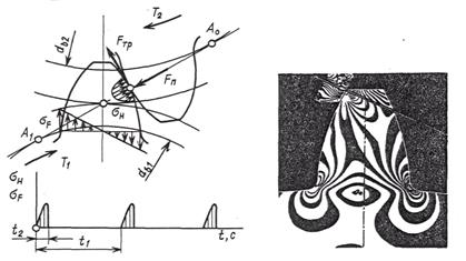
Two main stresses have a decisive influence on its performance: contact stress σ H and bending stress σ F. For each tooth, these stresses vary in time over an intermittent, nebulized cycle (see Fig. 7, a). The duration of stress for one revolution of the wheel (t 1) is equal to the duration of the engagement of one tooth (t 2).
Variable stresses cause fatigue destruction of teeth: tooth breakage due to bending stresses (Fig. 8, a), chipping of the tooth surface from contact stresses (Fig. 8, b), wear is also associated with contact stresses and friction in engagement ( c) jamming and other damage to the surface of the teeth.
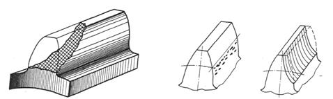
Fig. 8. Types of damage to the teeth
Calculation on contact strength is essential for closed (operating under heavy lubrication conditions) gears. The purpose of the calculation is to prevent fatigue chipping of the working surfaces of the teeth for a given service life. The bending calculation is essential for open gear teeth with high surface hardness. The purpose of the bending calculation is to prevent tooth breakage.
Pay attention to the determination of the forces acting in the gears and which are the initial for calculating the teeth, shafts and the selection of bearings. It should be remembered that the calculation of gears is performed on the design loads. These loads are greater than the nominal (theoretical) ones, since due to the deformation of the wheels, shafts, bearings, body parts and the inevitable errors in their manufacture and installation, additional dynamic loads occur. Design load
where T, F t - rated load (torque on the shaft and the circumferential force); K - coefficient of calculated load
K β - coefficient of concentration of the load, depends mainly on the asymmetry of the location of the wheels relative to the supports and the relative width of the wheel Ψ bd=, which affect the deformation of the parts and the misalignment of the tooth; K υ - coefficient of dynamic load, depends mainly on the peripheral speed and precision manufacturing gears; K β, K υ choose according to tables and graphs.
In the design calculation take approximately K = 1.1 ... 1.5. Smaller value is taken when working on materials (HB ≤ 350) with symmetric arrangement of wheels for indirect teeth.
Understand that choosing the right material for gears determines the size and cost of transmission. Steel is currently the main material for the manufacture of gears. Unless there are special requirements regarding the dimensions of the transfer, materials with average mechanical characteristics should be chosen, with a hardness of ≤ 350 NB (heat treatment normalization or improvement). This ensures perfect cutting of the teeth after heat treatment, high precision manufacturing and good workability of the teeth.
For uniform wear of the teeth and better workability, the hardness of the gear NB 1 is assigned more than the hardness of the wheel NB 2 on (20 ... 50) NB.
The choice of material, heat treatment and hardness. Table 9
| Parameter | For gears with straight and indirect teeth at low (P≤2 kW) and medium (P≤10 kW) power; HB 1cr -HB 2cp = 20 ... 50 | For gears with indirect teeth with average (P≤10 kW) power; HB 1 avg -HB 2cp ≥70 | |||
| Gear, Worm | Wheel | Gear, Worm | Wheel | ||
| Material | Steel 35, 40, 45, 40X, 40HN, 35XM | Steel 40X, 40XH, 35XM | |||
| Heat treatment | Improving Normalization | Improved + + hardening HD | Improvement | ||
| Hardness | ≤350НВ | ≥45 HRC u | ≤350 HB | ||
| Allowable voltage when the number of cycles of voltage changes N HO; N fo , N / mm 2 | [σ] Ho | 1.8NV Wed +67 | 14HRC esr + +170 | 1.8 HB Wed + +67 | |
| [σ] Fo | 1,03 HB Wed | when m ≥ 3 mm | 1,03 HB Wed | ||
| with m < 3 mm | |||||
Notes: l. In gear gears, make steels gears and wheels to choose the same. At the same time, for gears whose dimensions do not impose high requirements, cheap brands of 40, 40X type steels should be used. 2. For wheels of large-diameter open gears (D≥500 mm), use steel casting (35L, 40L, 45L, 40GL, heat treatment - normalization, improvement) together with forged gear made of steel of the corresponding brand.
The allowable contact stresses in the calculation of contact strength are determined separately for gear teeth [σ] H 1 and wheels [σ] H 2.
Mechanical characteristics of steel. Table 10
| steel grade | D before mm | S prev mm | Heat treatment | Workpiece hardness | σ in | σ t | σ -1 |
| Surface and core | N / mm 2 | ||||||
| Any | Any | H | 163 ... 192 HB | ||||
| Have | 192 ... 228 HB | ||||||
| Any | Any | H | 179 ... 207 HB | ||||
| Have | 235 ... 262 HB | ||||||
| Have | 269 ... 302 HB | ||||||
| 40X | Have | 235 ... 262 HB | |||||
| 40X | Have | 269 ... 302 HB | |||||
| 40X | U + HDTV | 269 ... 302 HB | |||||
| 40XH | Have | 235 ... 262 HB | |||||
| 40XH | Have | 269 ... 302 HB | 920" | ||||
| 40XH | U + HDTV | 269 ... 302 HB | |||||
| 35XM | Have | 235 ... 262 HB | |||||
| 35XM | Have | 269 ... 302 HB | |||||
| 35XM | U + HDTV | 269 ... 302 HB | |||||
| 35 l | Any | Any | H | 163 ... 207 HB | |||
| 40L | » | » | H | 147 HB | |||
| 45L | Have | 207 ... 235 HB | |||||
| 40GL | Have | 235 ... 262 HB |
Notes: 1.In the column "Heat treatment" the following notation is used: H-normalization, Y-improvement, high-frequency hardening by high-frequency currents. 2. For cylindrical and bevel gears, connect smaller values with zag, S zag.
[σ] H 1 = K HL 1 [σ] HO 1; [σ] H 2 = K HL 2 [σ] HO 2
where [σ] H 01, [σ] H 02 is the permissible contact stress corresponding to the limit of contact endurance at the number of cycles of voltage change N HO (Table 11); K HL - durability coefficient
K HL = ,
where N is the number of voltage cycles for the entire service life
N = 573ω h L h,
where ω is the angular velocity of the corresponding shaft, s -1; L h - service life of the drive, hours.
The definition of K HL taking into account the drive load curve is given in the literature / 2 / c 15 ... 16.
For normalized and improved wheels 1,0≤ K HL ≤2,6.
If N\u003e N HO, then take K HL = 1.
The value of the number of cycles N HO. Table 11
Cylindrical and bevel gears with straight and indirect teeth at HB 1cr -HB 2cp = 20 ... 50 are calculated by the smaller value [σ] H, i.e. on less strong teeth of gear pair.
Gears with indirect teeth with HB 1cr -HB 2cp ≥70 and wheel hardness ≤ 350 NB are calculated from the average allowable contact voltage
[σ] H = 0.45 ([σ] H 1 + [σ] H 2),
at the same time [σ] H must not exceed 1.23 [σ] H 2.
The allowable stress when calculating the bend is determined for the gear and wheels separately
[σ] F 1 = K FL 1 [σ] F 01; [σ] F 2 = K FL 2 [σ] F 02,
where [σ] F 0 is the allowable bending stress, which corresponds to the bending endurance limit with the number of stress change cycles N fo (Table 9); K fl - the coefficient of durability
K FL= ,
where N F 0 is the number of voltage change cycles corresponding to the fatigue limit. For all steels N fo = 4 ∙ 10 6. With a hardness of HB≤ 350.
1 ≤ K FL ≤ 2.08.
If N\u003e N F 0, take K fl = 1.
When designing a spur gear, follow the sequence below.
1. Select a material for gear and determine the allowable stress for the calculation of the contact endurance and bending.
2. Determine the transmission center distance a w, mm
a w = K a (u + 1)  ,
,
where K a = 43 for helical and chevron gears;
K a = 49.5 for spur;
Ψ a= - the ratio of the width of the crown wheel;
Ψ a are taken from a number of standard numbers: 0.1; 0.15; 0.2; 0.25; 0.315; 0.4; 0.5; 0.63, depending on the position of the wheels relative to the supports: with a symmetrical arrangement of 0.4 ... 0.5; with asymmetrical 0.25 ... 0.4; with the console 0.2 ... 0.25.
u- gear ratio; T 2 - torque on the low-speed shaft of the gearbox, H ∙ m; [σ] H is the permissible contact stress; K n b - load concentration factor. For running teeth at constant load K H b = 1.
The resulting value of the axial spacing a w rounds to the nearest value from a series of normal linear dimensions (Table 1H).
3. Determine the engagement module m, mm
m ≥ 
where K m = 6,8 - for spur gears; K m = 5.8 - for helical and chevron;
d 2 = pitch diameter of the wheel, mm; b 2 = Ψ a ∙ a w is the width of the crown of the wheel, mm;
[σ] F is the allowable stress of bending of the wheel material with a less durable tooth, N / mm 2.
Determine the module of the link from the condition m = (0.01 ... 0.02) and choose its value from the standard number series of numbers (not less than previously calculated).
m, mm 1st row -1.0; 1.5; 2; 2.5; 3; four; five; 6; eight; ten
2nd row -I, 25; I, 75; 2.25; 2.75; 3.5; 4.5; 5.5; 7; 9
When choosing a module, the 1st ~ row is preferable. In power gears with HB≤ 350, take m\u003e 1 mm.
4. To determine the angle of inclination of the teeth β min for helical gear and chevron gears
β min = arcsin.
In helical gear take β = 8 ° ... 20 °; in chevron - β = 25 ° ... 40 °.
5. Determine the total number of gear teeth and wheels for spur gears Z ∑ = Z 1 + Z 2 =; for helical and chevron Z ∑ = Z 1 + Z 2 = ![]() .
.
The resulting value of Z ∑ is rounded to the nearest side to an integer.
6. To clarify the actual value of the angle of inclination of the tooth.
Accuracy of calculating the angle β to the fifth decimal place
7. Determine the number of gear teeth
The value of Z 1 is rounded to the nearest integer. From the condition of noise reduction and absence of tooth trimming, it is recommended: Z 1 ≥17.
When getting Z 1 ≤17, take Z 1 = 17, or design the cutting teeth with a positive tool offset. The method of calculating such gearing can be found in the literature: / 2 / c 21 ... 22.
8. Determine the number of teeth of the wheel.
Z 2 = Z ∑ -Z 1.
9. Determine the actual gear ratio u f and check its deviation Δu from the given u: u f =;
Δu = ![]() ≤ 4% .
≤ 4% .
10. Determine the actual center distance:
a w = - for spur gears;
a w =  - for helical gears.
11. To determine the main geometrical parameters of the transmission according to the formulas given in table. 12.
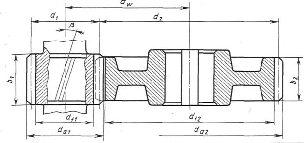
Fig. 9. Geometric parameters of a cylindrical gear.
Accuracy of calculation of wheel diameters up to 0.01 mm. The width of the gear rims is rounded to a whole number by normal linear dimensions (Table 1 P).
Geometric parameters of gears. Table 12
Verification calculation
12. Check center distance:
13. Check the suitability of the wheel blanks (see Table 10).
14. Check the contact stresses σ H, N / mm 2:
σ H = K 
where K = 436 for spur gears; K = 376 for helical and helical gears.
F t = is the external force in the mesh, N;
K N a is the coefficient taking into account the distribution of the load between the teeth; K H a = 1 - for spur gears; for helical gears, K N a is determined according to the graph in Figure 10, depending on the peripheral speed of the wheels v =, m / s and the degree of accuracy of the transmission (Table 13); K Hυ-dynamic load factor (tab. 14).
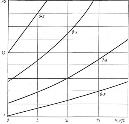
Fig. 10 Graph for determining the coefficient K H a according to the curves of the degree of accuracy
Underload of transmission is allowed (σ H<[σ] H) не более 15 %, перегрузка (σ H >[σ] H) up to 5%. If the condition is not met, increase the axle spacing a w, the width of the wheels or designate other wheel materials or other heat treatment, recalculate the allowable stresses and repeat the entire transfer calculation.
15. Check the bending stress of the gear teeth σ F 1 and wheel σ F 2, H / mm 2: σ F 2 = Y F 2 ∙ Y β ∙ K F a ∙ K Fβ K Fυ ≤ [σ] F 2;
σ F 1 = σ F 2 ∙ ≤ [σ] F 1,
where m is the gearing module, mm; b 2 - width of the gear rim of the wheel, mm; F t is the external force in the engagement, H; K F a = 1 for spur gears. For helical and chevron, depending on the degree of accuracy:
The values of the coefficients K Hυ and K Fυ when HB 2 ≤350. Table 14
| Degree of accuracy | Coefficient | Peripheral speed v , m / s | |||||
| K Hυ K F υ | 1,03 1,01 1,06 1,02 | 1,06 1,02 1,13 1,05 | 1,12 1,03 1,26 1,10 | 1,17 1,04 1,40 1,15 | 1,23 1,06 1,58 1,20 | 1,28 1,07 1,67 1,25 | |
| K Hυ K F υ | 1,04 1,02 1,08 1,03 | 1,07 1,03 1,16 1,06 | 1,14 1,05 1,33 1,11 | 1,21 1,06 1,50 1,16 | 1,29 1,07 1,67 1,22 | 1,36 1,08 1,80 1,27 | |
| K Hυ K F υ | 1,04 1,01 1,10 1,03 | 1,08 1,02 1,20 1,06 | 1,16 1,04 1,38 1,11 | 1,24 1,06 1,58 1,17 | 1,32 1,07 1,78 1,23 | 1,4 1,08 1,96 1,29 | |
| K Hυ K F υ | 1,05 1,01 1,13 1,04 | 1,1 1,03 1,28 1,07 | 1,2 1,05 1,50 1,14 | 1,3 1,07 1,77 1,21 | 1,4 1,09 1,98 1,28 | 1,5 1,12 2,25 1,35 |
Note. The numerator provides data for spur in the denominator - for helical gears and wheels with circular teeth.
K Fβ = 1 - for running teeth; F u -to table 13; Y F 1 and Y F 2 the coefficients of the shape of the tooth are determined according to Table 15, depending on the number of gear teeth Z 1 and the wheel Z 2 for spur gears. For helical gears and chevron wheels - depending on the equivalent number of gear teeth Z υ 1 = and wheels Z υ 2 =; Y β = 1 - for spur gears; Y β = 1- for helical gears;
[σ] F 1 and [σ] F 2 - allowable stress gear and wheels, N / mm 2.
Tooth shape factors Y F 1 and Y F 2. Table 15
| z or z υ | Y f | z υ | Y f | z υ | Y f | z υ | Y f | z υ | Y f | z υ | Y f |
| 4,28 | 3,92 | 3,80 | 3,66 | 3,61 | 3,62 | ||||||
| 4,27 | 3,90 | 3,78 | 3,65 | 3,61 | ∞ | 3,63 | |||||
| 4,07 | 3,88 | 3,75 | 3,62 | 3,60 | |||||||
| 3,98 | 3,81 | 3,70 | 3,62 | 3,60 |
Note. The tooth shape factors Y F correspond to the tool offset factor x = 0.
If, in the test calculation, σ F is significantly less than [σ] F, then this is permissible, since the loading capacity of closed gears is limited by the contact strength.
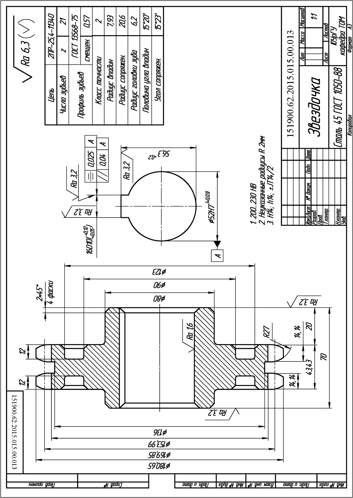
The calculation of the parameters of the asterisk is made depending on the size, parameters of the drive chain, double-row 2PR-25.4-11340 GOST 13568-75.
An example of a drawing of an asterisk (Appendix 7). Chain Transfer Ratio i= 3, the chain pitch is 25.4 mm.
The diameter of the pitch circle of the asterisk leading
where t - chain pitch;
z 1 - the number of teeth of the drive sprocket;

The diameter of the circle protrusions
The diameter of the circle of the hollows of an asterisk
 ,
,
where r=0,5025d 1 –0.05 is the radius of the depressions;
d 1 - the diameter of the roller chain (table 17) d 1 =15,88.
Diameter of groove  ,h= 24.2 is the width of the chain plates,
  mm
mm
Table 17
Circuit parameters
| Chain designation | tmm | d 1 mm | AT vn, mm | BUTmm | hmm |
| 2PR-12.7-3180 | 12,7 | 8,51 | 7,75 | 13,92 | 11,8 |
| 2ПР-15,875-4540 | 15,875 | 10,16 | 9,65 | 16,92 | 14,8 |
| 2PR-25.4-11340 | 25,4 | 15,88 | 15,88 | 29,29 | 24,2 |
| 2PR-19,05-8120 | 19,05 | 11,91 | 12,7 | 25,5 | 18,2 |
| 2PR-31.75-17700 | 31,75 | 19,05 | 19,05 | 38,15 |
Note. in the designation of the chain, numeral 2 indicates a double-row chain; for a single-row chain, the value of A is the distance between the rows of chain rollers equal to 0.
Sprocket tooth width mm.
Sprocket width for double row mm.
Rim thickness mm.
Release diameter to facilitate mm sprocket.
The thickness of the disk mm.
Construction of the tooth profile of an asterisk (Fig. 53).
The coordinate of the radius of curvature mm.
Tooth radius in longitudinal section mm.
Tooth width mm.

Fig. 53. Star parameters:
a) front view; b) side view
Calculation of parameters of the V-belt pulley
Belt drives refer to gears with flexible coupling, through which it is possible to ensure the infinitely variable transmission ratio (Variator Appendix 15). An example of drawing a pulley for a V-belt transmission is given in Appendix 8.
The calculation of the parameters of the V-belt pulley is determined by the cross section of the GOST 1284-68 belt.
For the belt section 0, the calculated diameter of the pulley leading d 1 is determined from the standard range: 63, 71, 80, 90, 100, 112, 125, 140, 160, 180, 200, 224, 250. External pulley diameter = 125 mm.
Depending on the cross section of the belt (Table 18)
 = 125 + 2 × 2.5 = 130mm,
Choose a table. nineteen.
Table 18
Main dimensions of V-belts
 |
|||||||||
| Type of | Designation | Sizes of section | Amm 2 | Lm | d 1min, mm | T 1, N × m | |||
| b | b etc | h | y 0 | ||||||
| Normal section | ABOUT | 8,5 | 2,1 | 0,4...2,5 | £ 30 | ||||
| A | 2,8 | 0,56...4,0 | 15...60 | ||||||
| B | 10,5 | 0,8...6,3 | 50...150 | ||||||
| AT | 13,5 | 4,8 | 1,8...10 | 120...600 | |||||
| R | 6,9 | 3,15...15 | 450...2400 | ||||||
| D | 23,5 | 8,3 | 4,5...18 | 1600...6000 | |||||
| E | 6,3...18 | ³4000 | |||||||
| Narrow | PP | 8,5 | 2,0 | 0,63…3,55 | £ 150 | ||||
| UA | 2,8 | 0,8…4,5 | 90…140 | ||||||
| Ub | 3,5 | 1,25…8,0 | 300…2000 | ||||||
| HC | 4,8 | 2,0…8,0 | ³1500 |
Table 19
The parameters of the cross section of the belt and the size of the grooves of the pulley
| Belt section | W p | b min | h min | e | f | r | d pfor the corner of the groove a | |||
| 34º | 36º | 38º | 40º | |||||||
| ABOUT | 8,5 | 2,5 | 7,0 | 12,0 | 8,0 | 0,5 | 50…71 | 80…100 | 112…160 | ³180 |
| BUT | 3,3 | 8,7 | 15,0 | 10,0 | 1,0 | 75…112 | 125…160 | 180…400 | ³450 | |
| B | 4,2 | 10,8 | 19,0 | 12,5 | 1,0 | 125…160 | 180…224 | 250…500 | ³560 | |
| AT | 5,7 | 14,3 | 25,5 | 17,0 | 1,5 | – | 200…315 | 355…630 | ³710 | |
| R | 8,1 | 19,9 | 37,0 | 24,0 | 2,0 | – | 315…450 | 500…900 | ³1000 | |
| D | 9,6 | 23,4 | 44,5 | 29,0 | 2,0 | – | 500…560 | 630…1120 | ³1250 | |
| E | 12,5 | 30,5 | 58,0 | 38,0 | 2,5 | – | – | 800…1400 | ³1600 |
Mm inner diameter accept d in = 110 mm.
Pulley rim width:
where z - number of belts (grooves);
e - step between grooves;
f - distance from rim edge.
Options e, f are shown in fig. 54.
Rim thickness for V-belts.
Sample diameter mm.
Mm hub length, d- diameter of the hole of the hub pulley.

Fig. 54. The profile of the grooves of the pulleys
Bibliographic list
1. Enterprise Standard. Course and diploma design. General requirements for registration: a tutorial / T.I. Steam Room, N.V. Syreyshchikova, V.I. Guzeev, L.V. Vinokourov. - 4th ed., Pererab. and add. - Chelyabinsk: Publishing house of SUSU, 2008. - 56 p.
2. Modern engineering. Machine parts and design fundamentals: textbook / PN. Uchaev, S.G. Yemelyanov, E.V. Pavlov et al. - Moscow: Akademiya, 2008. - 352 p.
3. Anurev, V.I. Reference book of the designer-mechanical engineer: 3 t. / V.I. Anurev / ed. I.N. Zhestkova. –8th ed., Revised and add. - M .: Mashinostroenie, 2001. –T.1. –920с.; Т.2. - 912 s .; V.3. –864s
4. Lelikov, O.P. Fundamentals of calculation and design of parts and components of machines: lecture notes for the course “Machine parts” / О.P. Lelikov. - 2nd ed., Pererab. and additional. - M .: Mashinostroenie, 2004. - 440 p.
5. Dunaev, P.F. Designing units and parts of machines: a manual for engineering specialties of universities / PF. Dunayev, O.P. Lelikov. - M .: Academy, 2004. - 496 p.
6. Scheinblit, A.E. Course design of machine parts: study guide / A.E. Scheynblit. - Kaliningrad: High School, 2002. - 455 p.
7. Akhlyustina, V.V. Machine parts. Calculation of mechanical gears. Designing chain transmissions: a tutorial / V.V.Akhlyustina, E.R. Logunova. - Chelyabinsk: Publishing house, 2008. - 135 p.
8. Ustinovsky, E.P. Multivariate design of cylindrical gear, bevel and worm gears with the use of computers: a manual for course design / E.P. Ustinovsky, Yu.A. Shevtsov, Yu.K. Yashkov. - Chelyabinsk: CSTU, 1995. - 105 p.
9. Sokhrin, P.P. Technical documentation in course design for machine parts: guidelines. P.P. Sokhrin, E.P. Ustinovsky, Yu.A. Shevtsov / ed. P.P. Sohrina. - Chelyabinsk: Chelyabinsk State Technical University, 1994. - 73 p.
10. Akhlyustina, V.V. Metrology, standardization and certification: a tutorial / V.V.Akhlyustina, E.R. Logunova. –Chelyabinsk: Publishing house of SUSU, 2008. - 211 p.
Applications
Annex 1
Appendix 3
Appendix 5
Appendix 7
Appendix 8
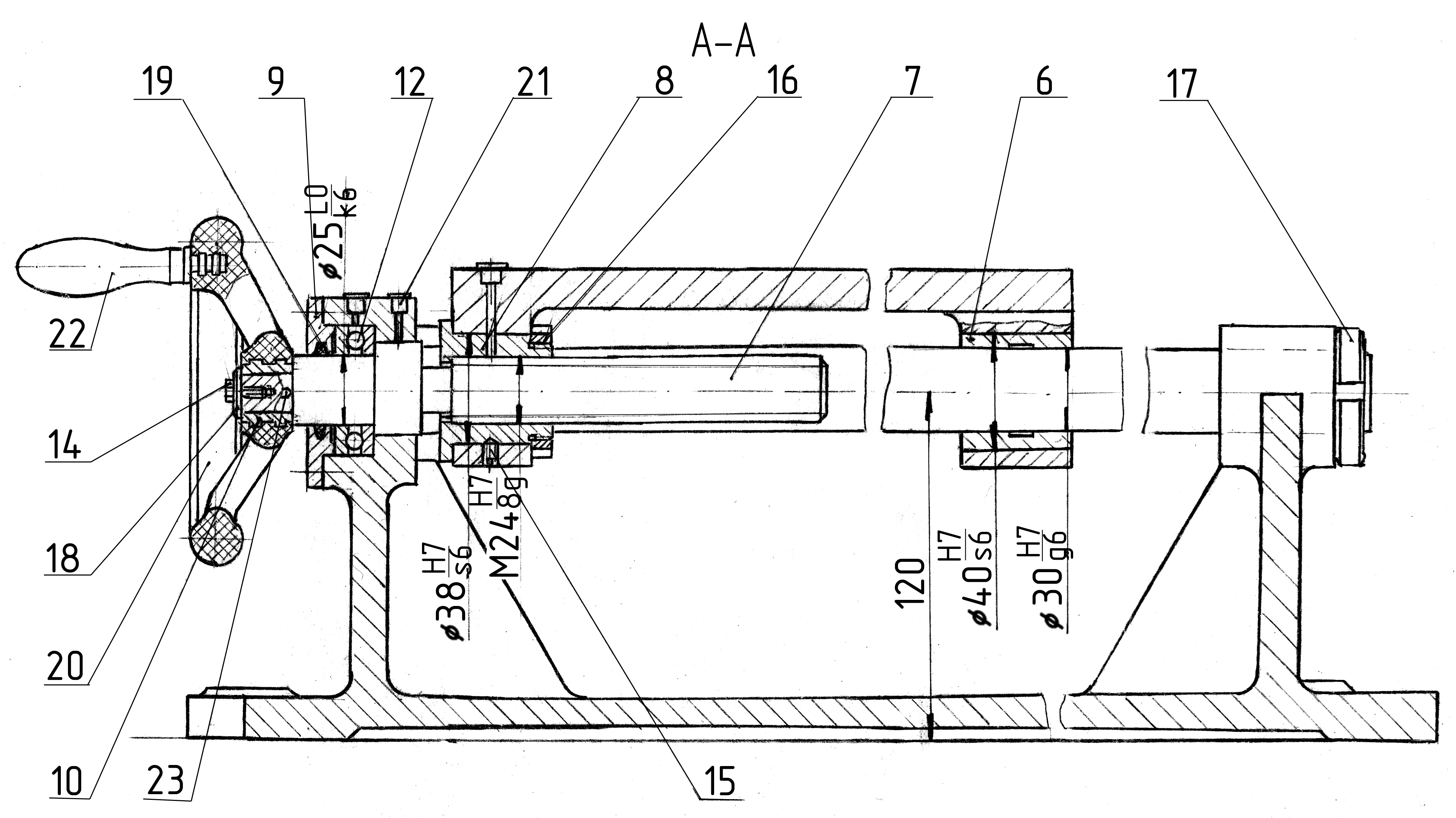
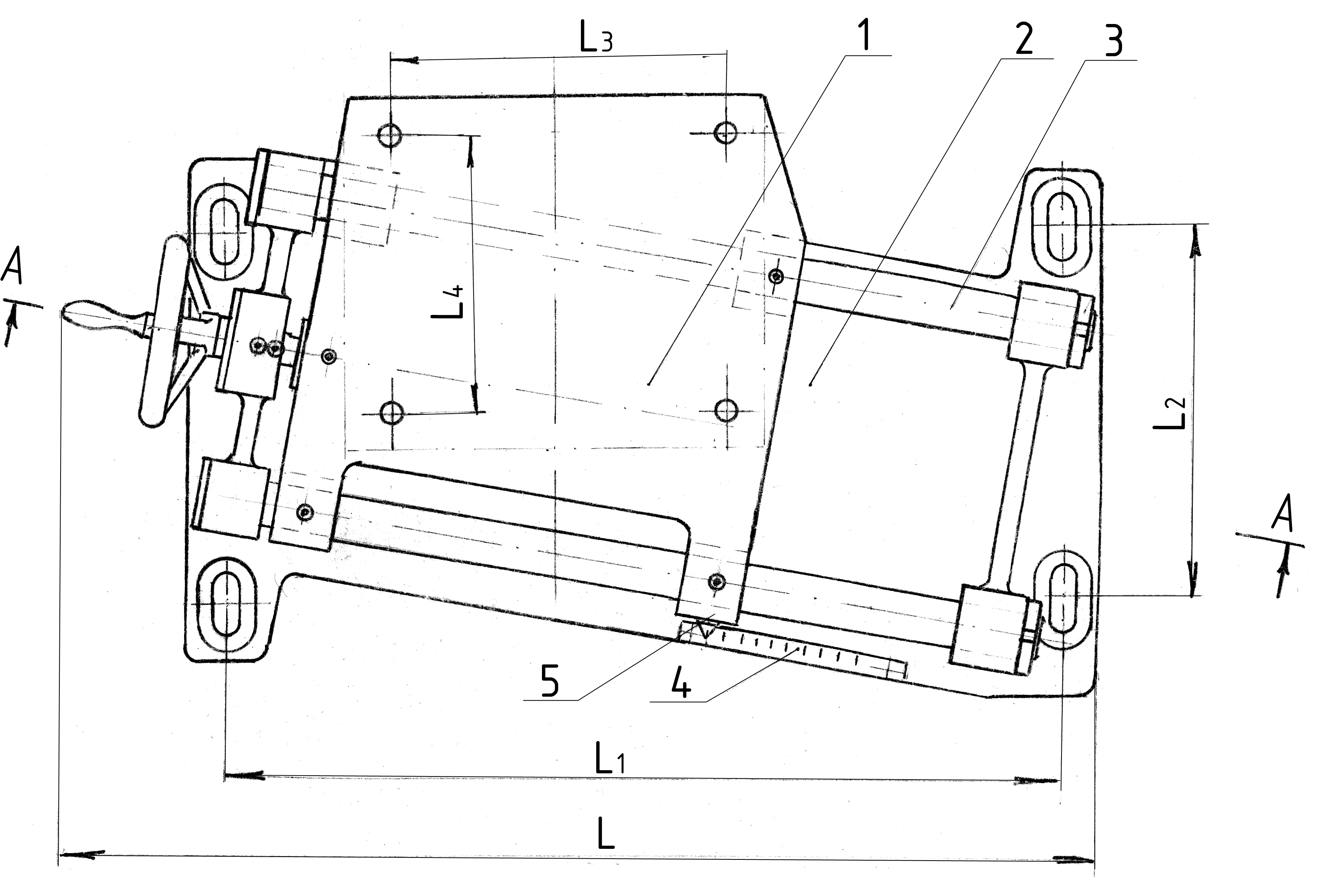
1. Tolerance of the coaxiality of the sliding bearings pos. 6, 8, 0.04 mm.
2. The tolerance of parallelism of the guides of position 3, 0.05 mm.
3. Adjust the position of the slide position 1, to provide a screw pos.7.
4. Sliding bearings position 6.8 and rolling elements position 9, lubricate CIATIM 201 GOST 6267-74.
Appendix 11
Pusher to butt welding machine