General information and classification of gears. Gears
Gears
Constructions
Replacement and repair of gears
Methods with crust repair gears
Gears
Worn and repaired gears
References
1. GEARS
1.1 Constructions
Gears are used in almost all the mechanisms with which metallurgical workshops are equipped (cranes and elevators, roller tables, winch-throw devices, mill drives, etc.)
The main parts of gears are cogwheels (gears). They serve to transfer rotation from one shaft to another when the shafts are not on the same axis.
Depending on the relative position of the shafts, gears are used: cylindrical, conical and helical.
A cylindrical gear drive serves to transfer rotation from one to another parallel shaft (Fig. 1, a).
The bevel gear transmission serves to transfer the rotation from the shaft to the shaft, located with the intersection of the axes (Fig.1,6).
The helical gear is used to transfer the rotation from the shaft to the shaft, located with intersecting, but not intersecting axes (Fig. 1, c).
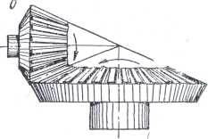
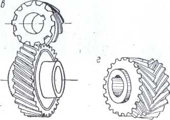
Fig. 1. Gears: a - cylindrical: b - bevel: in - screwing: g-chevron gear.
The gear wheel and the rake are used to convert the rotational movement in the progressive-return
The teeth of the cylindrical wheels can be straight (Fig. 1, a and b), oblique and chevron (Christmas) - Fig. 1,
Chevron gear consists of two gears with oblique teeth connected together.
When gear wheels with straight teeth are engaged, one or two teeth are simultaneously engaged, as a result of which the work of the transfer is accompanied by some jerks.
A smoother gear operation is achieved by using oblique or chevron teeth, since the number of teeth involved in the engagement increases.
Gear wheels are made from steel forgings, steel castings and rolled products or from iron castings. For critical gears (for example, lifting machines) the use of cast-iron gears is not allowed.
The classification of gears. Depending on the purpose of the gear, the type of the tooth and the speed of rotation, the gears are divided into four classes of accuracy of gears according to the tolerances for production and assembly (Table 119).
Table 1 Classification of gears
|
Allowable |
||||
|
Type of gear |
district speed |
Note |
||
|
growth, m / s |
||||
|
Cylindrical |
Apply where accuracy |
|||
|
and smoothness do not have |
||||
|
values as well as in |
||||
|
Conic |
manual and non-loaded |
|||
|
gears |
||||
|
Cylindrical |
||||
|
Conic |
||||
|
Cylindrical " |
||||
|
Conic |
||||
|
Cylindrical |
1 With the requirements of large |
|||
|
1 smooth transmission |
||||
|
Conic |
whether as well as in counting |
|||
|
mechanisms |
Gears make open, half-open and closed.
Open called transfer, which do not have a casing (tank) for the oil bath; such gears are lubricated periodically with grease. Usually these gears are low-speed and are used primarily in simple machines and mechanisms.
Semi-open gears differ from the open ones by the presence of a tank for a liquid oil bath.
Closed call transmission, which, together with the bearings are mounted in special housings.
Gearbox gears are lubricated in various ways:
1) at circumferential speeds of gears above 12--14 m / sec-jet method with the supply of a jet to the zone of the beginning of gearing of gear wheels;
2) at peripheral speeds of gears below 12 m / s - by dipping.
When lubricating by dipping, the following should be considered:
a) the larger gear of the pair must be immersed in the oil two to three times the height of the tooth;
b) if the gearbox has several stages, the oil level is determined taking into account the speed of transmission.
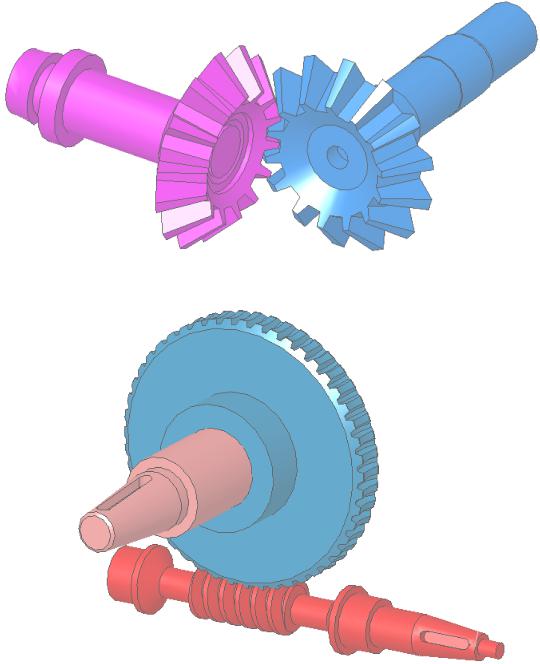
In the latter case, level b (fig. 2) is allowed when the gear wheel of a low-speed stage rotates at a low speed. In gearboxes with medium and large
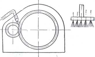
Fig. 2. Jet grease gears.
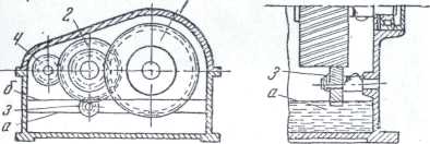
Fig. 3. Scheme lubrication gear dipping.
the speeds of low wheels, the latter are immersed at two to three times the height of the tooth of the larger wheel, and the oil is poured to level a. lubrication of the first stage put an auxiliary gear wheel 3 with a narrow tooth, which supplies lubricant to the impeller.
The viscosity of the oil poured into the gearbox is chosen depending on the speed and load — usually from 4 to 12 ° E at a temperature for determining the viscosity of 50 ° C. The temperature conditions in which the unit operates are also taken into account; at higher temperatures, an oil of higher viscosity is used, at lowering, a lower viscosity.
Open gears are usually lubricated with grease (grease, constantin, etc.).
Packing seals provided (drawings) in the bearings and along the line of the gearbox housing, should be done very carefully to avoid oil leakage and dust in the gearbox.
Worn and repaired gears
Gears fail for two main reasons: the wear of the teeth and their breakdowns.
Wear is usually the result of: 1) incomplete adhesion and 2) increased friction (gradual wear).
Wear in the first case is mainly the result of poor installation and with proper assembly (strict observance of the radial clearance) is usually absent. However, a change in the radial clearance can also be a consequence of the development of bearing shells, and as a result of the development of bearings, there can be either an increase in the radial clearance or a decrease in it (operation).
If the load on the liners is transmitted to the sides, opposite to the coupling in the process of work as the liners are developed, an increase in the radial clearance is possible.
If the load on the liners is transferred to the side of the cordon (for example, at the gears of the crane sliders, in the process of working as the liner is developed (in this example of the slider liner), the radial clearance may be reduced.
In both cases, after the liner change, the radial clearance is restored.
Gradual wear from increased friction depends on a number of conditions, including the hardness of the material from which the gears are made, heat treatment, the correct selection of lubricant, insufficient cleanliness of the oil and untimely changing it, transfer overload, etc.
Proper installation and good supervision during operation are the main conditions for long and uninterrupted equipment operation.
Gear teeth failures occur for the following reasons: overloading gears, one-sided (from one end of the tooth) load, undercutting of the tooth, imperceptible cracks in the workpiece material and microcracks, as a result of poorly performed heat treatment, weak resistance of the metal to jolts (in particular, as a result of non-annealing of castings and forgings), increased shocks, hit between the teeth of solid objects, etc.
2.1 Replacing and repairing gears.

Fig. 4. Repair of the teeth with the help of screwdrivers followed by welding
As a rule, gears with worn and broken teeth are not to be repaired, but replaced, and it is recommended to replace both wheels at the same time. However, when a large wheel in the gearing is many times larger than the small one, it is necessary to replace the small wheel in a timely manner, which wears out faster than the large one by about a gear ratio. Timely replacement of the small wheel will protect the large wheel from wear.
The wear of the gear teeth should not exceed 10-20%: the thickness of the tooth, counting along the arc of the initial circle. In low-response gears, tooth wear is allowed up to 30% of tooth thickness, in gears of responsible mechanisms it is much lower (for example, for load lifting mechanisms, wear should not exceed 15%: tooth thickness, and in gear wheels of crane lifting mechanisms transporting liquid and hot metal - to 10%").
Gears with cemented teeth should be replaced when the cementation layer is worn over 80% 1 of its thickness, as well as when cracking, chipping or peeling of the cemented layer.
If the teeth break, but no more than two in a row in not very important gears (for example, mechanisms of crane movement), they can be restored as follows: broken teeth are cut to the ground, two or three holes are drilled through the width of the tooth, and the threads are cut into them, they make the studs and screw them into the prepared holes, weld the studs to the gear, and weld the metal using electric welding, giving it the shape of a tooth, on a gear cutting, milling or planing machine or by handing attach weld metal tooth form and then reconstituted with a profile conjugate checked clutch piece and the template.
The sequence of tooth restoration operations by welding is shown in Fig. 298.
To facilitate the process of post-float treatment of the teeth of L-rare and large modules, it is recommended to weld them over
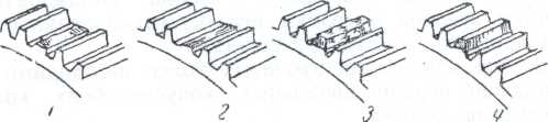
Fig. 5. The sequence of operations when welding teeth:
1 - broken tooth; 2- the place of the cut tooth; 3 - weld tooth on heels; 4- treated (sawed) tooth.
copper pattern (Fig. 299), the use of which is based on the fact that the copper pattern, having the shape of the pinions of the gear, forms the edges of the tooth. When welding, due to the high thermal conductivity of copper, the metal is not welded to the template and after surfacing the template is easily removed, and the weld metal is welded to form the shape of the tooth.
![]()
Fig. 6. The method of welding the teeth by welding:
1 - repair gear;
2 - weld tooth; 3 - copper pattern.
Surfacing should be carried out necessarily with high-quality (thick-greased) electrodes of the brand not lower. After surfacing, annealing is desirable.
For especially important mechanisms (for example, crane lifting mechanisms), surfacing (repair) of the teeth is not allowed, gear wheels in these cases should be replaced with new ones.
Do not fix the teeth of various kinds with screwdrivers without welding or into the groove in the form of a dovetail, as these methods are unreliable and do not ensure the normal operation of the equipment.
Gears with a bursting rim are usually repaired by arc welding, developing welding technology so that as a result of welding, additional stresses do not form that cause cracks in other wheel elements (it is recommended that the entire gear be heated to red hot, and also annealed after welding).
Gears with a crack in the hub are repaired by landing on a hub of a steel brace specially forged or cast and machined on a machine, heated to 300-400 ° C.
Gears of especially important gears (for example, crane lifting mechanisms) that have cracks in the “bode”, the spokes and the hub are replaced; repair by welding or another method is not allowed.
Gears rotating at high speeds, as well as large-diameter gears at medium speeds, must be subjected to static balancing.
2.2 Methods of speed repair gears
High-speed repair gears, as well as other items of equipment, according to. his technique must be nodal.
When high-speed nodal repairs replace individual gears or gears: not performed, they are replaced by pre-assembled nodes, and, as indicated earlier, when considering, the types of nodes as repair and installation units can be three:
large nodes, which include disputed cases
(for example, gearbox housings) and the whole range of gearing, mounted in these housings;
a group of interconnected with the help of gearing individual nodes (for example, shafts, pos. /, 2, 3, together with those; parts that are mounted on them);
individual individual nodes, which include gears.
Depending on the specific conditions characteristic of this repair, one of the specified types of nodal repair is accepted in the work organization plan.
The most qualitative is the high-speed repair carried out by replacing individual large nodes - gearboxes.
However, in this case, it is necessary that, firstly, the gearboxes to be dismantled and reassembled should be interchangeable, and, secondly, the corresponding rigging equipment should be prepared in advance.
Typification of gearboxes, i.e., approval for a given workshop or an enterprise as a whole of certain types and sizes of interchangeable gearboxes is the most important measure ensuring high-speed, high-quality repairs.
References
Assembly machines in heavy engineering / B.V. Fedorov, V.A. Vavulenko et al. 2nd ed. M .: Mash-e, 1987.
Handbook of technologist-machine builder: in 2 tons. Edited by AG Kosilova M .: Mash-e, 1985.
Metal cutting machines. Training Manual for technical colleges. N.S. Kolev and others. Moscow: Mash-ie, 1980.
Skhirtladze AG, Novikov V.Yu., Tulaev Yu.I. Technological equipment of machine productions. Training Benefit. M .: Publishing house "Stankin", 1997.
Similar essays:
Motor selection, kinematic calculation and drive circuit. Rotational speed and angular velocity of the shafts of the gearbox and the drive drum. Calculation gear gear. Tooth endurance on bending stresses. Calculation of the shaft torque.
Classification of gears for operational purposes. Tolerance system for spur gears. Methods and means of control of gears and gears. Devices for the control of spur gears, applied methods of their use.
Calculation of the service life of the drive unit. Engine selection, kinematic calculation of the drive. Selection of materials gears. Determination of allowable stresses. Calculation of a closed bevel gear. Determination of forces in gearing closed gears.
Study of the design of a cylindrical two-stage gearbox, measurement of overall and connecting dimensions. Determination of gearing parameters. The calculation of the permissible load from the conditions for ensuring the contact endurance of a gear.
Spur gearbox design. Drive motor selection. Estimated bending stress in a dangerous gear tooth section. Constructive dimensions of gears and body elements. The main parameters of the gear pair. Approximate calculation of shafts.
Kinematic, power calculations drive. Determination of power on the shaft of the actuator. Determination of the estimated power of the motor shaft. Determination of the shaft speed of the actuator. Calculation of closed cylindrical gears.
Swivel-lever mechanisms are used to convert rotational or translational motion into any movement with the required parameters. Friction - to change the speed of rotational motion or convert rotational to translational.
The study of the theoretical foundations of cutting gears by running a gear rack. Construction of wheel profiles using the device. Milling of teeth of a cylindrical wheel. The shape of the tooth depending on the offset. The position of the rail relative to the wheel.
Kinematic drive belt conveyor. Kinematic calculation of the electric motor. Determination of the required power of the electric motor, the results of kinematic calculations on the shafts, the angular velocity of the motor shaft. Calculation gear gear.
Description of the appearance of the gear mechanism. Kinematic calculation. Calculation of transmission geometry and its details. Power calculation mechanism. Calculation of gearing for strength, strength of one of the shafts of the mechanism. Selection of construction materials.
Determination of the estimated power of the motor, gear ratio drive. Calculation of power transmitted by the drive shafts and torques. The design calculation of low-speed and bevel gears, shaft bearings on the static load capacity.
Method of designing a three-stage cylindrical gearbox. The procedure for determining the allowable stresses. Features of the calculation of the 3-speed gearbox, intermediate shafts and bearings for them. Specificity of checking the strength of keyed joints.
Advantages and disadvantages of planetary gears over conventional ones, scope. The principle of operation and the main links of the planetary gears. Wave gears, design scheme, principle of operation, advantages and disadvantages of wave transmissions.
The parameters of the cylindrical helical gears. The designs and materials of gears, their size and shape. Bevel gears and its geometric calculation. The design and calculation of worm gears. The main advantages and disadvantages of worm gears.
Worm gear design. Design of a cylindrical gear. Calculation of the dead stroke of the gearbox. Precision gears and worm gears. The tolerances of the shape and location of the surfaces of gears, worms. Structural elements of the shaft.
Kinematic calculation of the transmission and selection of the electric motor. Calculation of the cylindrical transmission. Approximate calculation of shafts. Calculation of the main dimensions of the gear case. Selection of bearings and couplings. Selection of gear lubricant and bearings.
TOOTH TRANSMISSIONS
P l and l to c and u
1. General information.
2. Classification of gears.
3. Geometric parameters of gears.
4. Accuracy of parameter conversion.
5. Dynamic ratios in gears.
6. The design of the wheels. Materials and allowable stresses.
1. General information
GearIs a mechanism that, by means of a gearing, transmits or transforms motion with a change in angular velocities and moments. The gear train consists of wheels with teeth that interlock with each other, forming a series of successive cam mechanisms.
Gears are used to convert and transfer rotational motion between shafts with parallel, intersecting or intersecting axes, and also to convert rotational motion into translational and vice versa.
Advantages of gears:
1. Constancy of gear ratioi.
2. Reliability and durability of work.
3. Compactness.
4. Large range of transmitted speeds.
5. Low pressure on shafts.
6. High efficiency.
7. Ease of maintenance.
Disadvantages of gears:
1. The need for high precision manufacturing and installation.
2. Noise at high speeds.
3. The impossibility of infinitely variable transmission ratio
i.
2. Classification of gears
Gears used in mechanical systems are varied. They are used both to lower and to increase the angular velocity.
Classification of designs of gear converters groups transmissions in three ways:
1. By type of teeth engagement. In technical devices, transmissions with an external (Fig. 5.1, a), with an internal (Fig. 5.1, b) and with a rack (Fig. 5.1, c) gearing are used.
Transmission with external gearing is used to convert rotational motion with a change in direction of motion. The gear ratio ranges from –0.1 i –10. Internal gearing is used in the event that it is necessary to convert the rotational movement with preservation of direction. Compared to external gearing, the transmission has smaller overall dimensions, a greater overlap coefficient and increased strength, but is more difficult to manufacture. Rack gearing is used when converting rotational motion into translational and back.
2 By the mutual arrangement of the shaft axes distinguish transmission cylindrical wheels with parallel axes of the shafts (Fig. 5.1,but ), conical wheels with intersecting axles (fig. 5.2), wheels with intersecting axles (fig. 5.3). Gears with bevel gears have a lower gear ratio (1/6i 6) are more difficult to manufacture and operate, have additional axial loads. Screw wheels work with increased slip, wear faster, have a low load capacity. These gears can provide different gear ratios for the same wheel diameters.
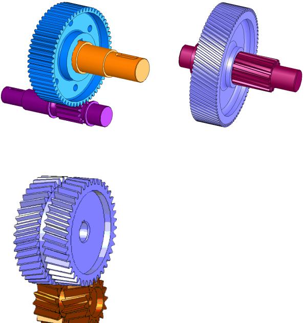
3 By the location of the teeth relative to the wheel forming the rim
there are spur gears (Fig. 5.4, a), helical gears (Fig. 5.4, b), chevron (Fig. 5.5) and with circular teeth.
Helical gears have large |
||||
shuya smoothness of engagement, less |
||||
technologically | equivalent |
|||
spur but in transmission arise |
||||
additional | load. |
|||
Dual helical gear | counter |
|||
tilted teeth (chevron) |
||||
cha has all the benefits of helical |
||||
and balanced axial forces. But |
||||
the transfer is somewhat more difficult to make |
||||
lenia and installation. Curvilinear |
||||
teeth are most often used in horse |
||||
gears | enhance |
|||
load capacity | smoothness |
|||
work at high speeds. |
||||
3. Geometric parameters of gears
TO the main geometrical parameters of gear wheels (Fig. 5.6) include: tooth pitchP t, mod m (m = P t /), number of teeth Z, diameter d of pitch circle, height h a of dividing head of a tooth, height h f of dividing leg of a tooth, diameters d a and d f of circles of peaks and hollows, width of a gear rimb.
df 1 | db 1 | |||
dw 1 (d1) | ||||
da 1 | ||||
df 2 | dw 2 (d2) | da 2 |
||
db 2 | ||||
The diameter of the pitch circle d = mZ. The pitch of the wheel tooth is divided into the pitch head and the pitch leg, the size ratio of which is determined by the relative position of the wheel and tool blank in the process of cutting teeth.
With a zero displacement of the initial contour, the height of the dividing head and the leg of the wheel tooth corresponds to those of the initial contour, i.e.
ha = h a * m; hf = (h a * + c *) m,
where h a * is the height factor of the tooth head; c * is the radial coefficient
For wheels with external teeth, the diameter of the circle tops
da = d + 2 ha = (Z + 2 h a *) m.
The diameter of the circumference of the hollows
df = d –2 hf = (Z –2 h a * –2 c *) m.
When m ≥ 1 mmh, a * = 1, c * = 0.25, d a = (Z - 2.5) m.
For wheels with internal teeth, the diameters of the circles of the tops and bottoms are as follows:
da = d –2 ha = (Z –2 h a *) m;
df = d + 2 hf = (Z + 2 h a * + 2 c *) m.
For wheels that are cut with an offset, the diameters of the tops and valleys are determined based on the magnitude of the offset coefficient for more complex dependencies.
If two wheels cut without displacement are engaged, then their pitch circles will touch, that is, they will coincide with the initial circles. The angle of engagement in this case will be equal to the angle of the profile of the initial contour, i.e. the initial legs and heads will coincide with the dividing legs and heads. The center distance will be equal to the divisional center distance determined through the diameters of the division circles:
aw = a = (d1 + d2) / 2 = m (Z1 + Z2) / 2.
For wheels cut with an offset, there is a difference for initial and pitch diameters, i.e.
d w 1 d 1; d w 2 d 2; a w a; αw = α.
4. Parameter Conversion Accuracy
AT during the operation of gears theoretically constant gear ratio undergoes continuous changes. These changes are caused by the inevitable errors in the manufacture of the dimensions and shape of the teeth. The problem of manufacturing gears with low sensitivity to errors is solved in two directions:
a) the use of special types of profiles (for example, hourly gearing);
b) limitation of manufacturing errors.
AT unlike simple parts such as shafts and bushings, gears are complex parts, and errors in the performance of their individual elements not only affect the pairing of two separate teeth, but also affect the dynamic and strength characteristics of the gear transmission as well as the accuracy transfer and transformation of rotational motion.
The errors of gears and gears, depending on their impact on transmission performance, can be divided into four groups:
1) errors affecting the kinematic accuracy, i.e. the accuracy of transmission and transformation of rotational motion;
2) errors affecting the smooth operation of the gear;
3) errors of contact stain teeth;
4) errors leading to a change in side clearance and affecting the dead stroke of the transmission.
In each of these groups, the complex errors that most fully characterize this group and element-by-element, partially describing the transmission performance indicators, can be distinguished.
This division of errors into groups is the basis for standards for tolerances and deviations of gears: GOST 1643–81 and GOST 9178–81.
To assess the kinematic accuracy of the transmission, smooth rotation, contact characteristics of the teeth and the dead stroke in the standards under consideration, 12 degrees of precision manufacturing gears are established
and gears. The degrees of accuracy in descending order are indicated by numbers. 1–12. Accuracy 1 and 2 according to GOST 1643–81 for m\u003e 1 mm and according to GOST 9178–81 for 0.1 It is allowed to use gear wheels and gears, the error groups of which may belong to different degrees of accuracy. However, a number of errors belonging to different groups in their influence on the accuracy of transmission are interrelated, therefore restrictions are imposed on the combination of accuracy standards. Thus, the norms of smoothness can be no more than two degrees more accurate or one degree rougher than the norms of kinematic accuracy, and the rates of contact of the teeth can be assigned to any degrees more accurate than the norms of smoothness. The combination of precision standards allows the designer to create the most economical transmissions, while choosing such degrees of accuracy for individual indicators telephones that meet the operational requirements for this transmission, not overestimating the cost of manufacturing the transmission. The choice of degrees of accuracy depends on the purpose, the field of application of the wheels and the peripheral speed of rotation of the teeth. Let us consider in more detail the errors of gears and gears that affect their quality. 5. Dynamic ratios in gears Gears transform not only movement parameters, but also load parameters. In the process of converting mechanical energy, a part of the power P Tr supplied to the input of the converter is expended on overcoming rolling and sliding friction in the kinematic pairs of gears. As a result, the output power decreases. To assess the loss power is used the concept of efficiency (EFFICIENCY), defined as the ratio of the output power of the converter to the power supplied to its input, i.e. η = P out / P in. If the gear drive converts the rotational motion, then, respectively, the input and output power can be defined as Denote ωout / ωin by i, and the value Tout / Tin in through i m, which we call the ratio of the moments. Then the expression (5.3) takes the form η = i m The value of η varies between 0.94–0.96 and depends on the type of transmission and the transmitted load. For gear cylindrical transmission, the efficiency can be determined from the dependence η = 1 - cf π (1 / Z 1 + 1 / Z 2), where c is a correction factor that takes into account a decrease in efficiency with a decrease in the transmitted power; 20T out 292mZ 2 20T out 17mZ 2 where T o is the output moment, H mm; f is the friction coefficient between the teeth. To determine the actual force on the gear teeth, consider rome is the process of load conversion (Fig. 5.7). Let the driving input moment T 1 be applied to the driving gear 1 with the diameter of the initial circle d w l, and the moment of resistance T 2 of the driven wheel 2 is directed in the direction opposite to the rotation of the wheel. In involute gearing, the contact point is always on the line, which is a common normal to the contact profiles. Consequently, the pressure force of the toothF of the drive wheel on the slave tooth will be directed along the normal. We will transfer the force along the line of action to the pole of the link and decompose it into two components. Ft ’ Ft ’ The tangent component of F t is called district force. She is performs useful work, overcoming the moment of resistance T and driving the wheels. Its value can be calculated by the formula F t = 2T / d w. The component vertically is called radial forceand is denoted by F r. This force of work does not make, it only creates an additional load on the shafts and transmission support. When determining the magnitude of both forces, friction forces between the teeth can be neglected. In this case, between the total pressure force of the teeth and its components, the following dependencies exist: F n = F t / (cos α cos); F r = F t tg α / cos, where α is the angle of engagement. The engagement of spur wheels has a number of significant dynamic disadvantages: limited overlap values, significant noise and shocks at high speeds. To reduce the size of the transmission and reduce the smoothness of the work, the spur gear is often replaced with a helical gear, the side profiles of the teeth of which are involute helical surfaces. In helical gears, the total force F is directed perpendicular to the tooth. We decompose this force into two components: F t is the circumferential force of the wheel and F a is the axial force directed along the geometrical axis of the wheel; F a = F t tg β, where is the angle of inclination of the tooth. Thus, in contrast to the spur gear, three mutually perpendicular forces F a, F r, F t, of which only F t does useful work, act in the helical engagement. 6. The design of the wheels. Materials and allowable stresses The design of the wheels.When studying the principles of designing gears, the main goal is to master the method of determining the shape and basic parameters of the wheels according to the conditions of operability and operation. The achievement of this goal is possible when solving the following tasks: a) selection of optimal wheel materials and determination of permissible mechanical characteristics; b) the calculation of wheel sizes according to the conditions of contact and bending strength; c) the design of gears. Gears are typical converters for which quite a lot of reasonable design optimal variants have been developed. The synthesis scheme of the gear design can be represented as a combination of three main structural elements: the ring gear, the hub and the central disk (Fig. 5.9). The shape and dimensions of the gears are determined depending on the number of teeth, module, shaft diameter, as well as the material and technology of manufacturing wheels. In fig. 5.8 shows examples of the designs of gears mechanisms. The dimensions of the wheels are recommended to take in accordance with the instructions of GOST 13733-77. Students, graduate students, young scientists who use the knowledge base in their studies and work will be very grateful to you. Posted at http://www.allbest.ru/ Gears Introduction gear wheel involute transmission The rapid development of science and technology leads to the emergence of new materials, new technological solutions allowing the creation of fundamentally new designs, but the fundamental methodological provisions remain unchanged. In the XI century, special attention was paid to the machine-building and aircraft-building industries, in this connection I would like to dwell on the general-purpose elements used in these industries, namely gears. In the abstract, the definition of gearing is given, their classifications, the method of calculating the geometrical parameters of gear wheels are considered. Also in this paper the assignment of a gear transmission is described, the transmission characteristics in the mechanisms are given. 1
.
Zoobchatoh wheel,
classification The gear, gear - the main part of the gear in the form of a disk with teeth on a cylindrical or conical surface that meshes with the teeth of another gear. In mechanical engineering, it is customary to call a small gear wheel with a smaller number of teeth a gear wheel, and a large gear wheel to be called a gear wheel. However, often all gear wheels are called gears. Fig. 1. Gear wheel Cogwheels are commonly used as pram with different numbers of teeth in order to convert the torque and the number of revolutions of the shafts in the input and output. The wheel, to which the torque is supplied from the outside, is called the driving one, and the wheel, from which the moment is removed, is driven. If the diameter of the drive wheel is smaller, then the torque of the driven wheel increases due to a proportional decrease in the rotational speed, and vice versa. In accordance with the gear ratio, an increase in torque will cause a proportional decrease in the angular velocity of rotation of the driven gear, and their product, the mechanical power, will remain unchanged. This ratio is valid only for the ideal case, which does not take into account friction losses and other effects typical of real devices. A) Transverse tooth profile The profile of the teeth of the wheels usually has an involute side shape. However, there are gears with a circular shape of the teeth profile (Novikov gear with one and two gearing lines) and cycloidal gears. In addition, gear wheels with asymmetrical tooth profiles are used in ratchet mechanisms. Gear parameters: m - wheel module. The engagement module is called a linear quantity in r times smaller circumferential pitch P or the ratio of the pitch along any concentric circle of the gear to r, that is, the module - the number of millimeters of diameter per one tooth. Dark and light wheels have the same module. The most important parameter, standardized, is determined from the strength calculation of gears. The more loaded the transmission, the higher the value of the module. All geometrical parameters of gearing are expressed through its module: 1. Tooth modulus m=
=
.
2. Heights of teeth h
=
2,25m.
3. The height of the tooth head h=
m.
4. Tooth height h=
2,25m.
5. The diameter of the pitch circle d
=
mz.
6. The diameter of the circle protrusions d=
d+
2
h =
d+
2m=
m(z+
2). 7. Diameter of a circle of hollows
d = d + 2
h = d + 2
m = m (
z + 2).
8. Radial clearance between mating rings with=0,25t. 9. Center distance a=
.
10. Tooth pitch p= pm.
11. Tooth thickness S=
0,5p=
.
12. Depth width l=
0,5p=
.
13. The width of the crown gears (tooth length) b?
(6…8).m 14. The diameter of the hub d?
(1,6…2)
d.
15. The length of the hub l=
1,5
d.
16. Rim thickness d
?
(2,5…4) m.
17. Angle of profile, angle of engagement b =
b
=
20. 18. Pitch diameter, initial diameter d =
d
=
mz.
19. The main diameter.
d
=
d cos b Fig. 2 Gear parameters In mechanical engineering, certain values of gearwheel module m are adopted for ease of manufacture and replacement of gears, which are integers or numbers with decimals: 0.5; 0.7; one; 1.25; 1.5; 1.75; 2; 2.5; 3; 3.5; four; 4.5; 5 and so on to 50. B) Longitudinal line of the tooth Gears are classified depending on the shape of the longitudinal line of the tooth into: spur gear, helical gear, chevron. B) Spur wheels Spur wheels - the most common type of gears. The teeth are located in radial planes, and the line of contact of the teeth of both gears is parallel to the axis of rotation. In this case, the axes of both gears should also be strictly parallel. Spur wheels have the lowest cost, but at the same time, the limiting torque of such wheels is lower than helical and helical gears. C) helical gear The helical wheels are an improved version of the spur gears. Their teeth are angled to the axis of rotation, and form part of a spiral in shape. Advantages: The engagement of such wheels occurs smoother than that of spur gears, and with less noise; The contact area is increased compared to the spur gear, so the limiting torque transmitted by the gear pair is also larger. During the operation of the helical gear, a mechanical force directed along the axis arises, which necessitates the use of thrust bearings for mounting the shaft; Increasing the friction area of the teeth (which causes additional power loss for heating), which is compensated by the use of special lubricants. In general, helical wheels are used in mechanisms that require the transmission of high torque at high speeds, or have severe restrictions on noise. D) Chevron wheels The teeth of these wheels are made in the form of the letter "V" (or they are obtained by joining two helical gears with a counter-arrangement of the teeth). Gears based on such gears are commonly referred to as "chevron". Chevron wheels solve axial force problem. Axial forces of both halves of such a wheel are mutually compensated, therefore, there is no need to install shafts on thrust bearings. In this case, the gear is self-aligning in the axial direction, for which reason in gearboxes with chevron wheels one of the shafts is mounted on floating supports (as a rule, on bearings with short cylindrical rollers). D) Gear wheels with internal gearing With strict limitations on the dimensions, in planetary mechanisms, in gear pumps with internal gearing, in the drive of the tank turret, wheels with a gear rim, cut from the inside, are used. Rotation of the driving and driven wheels is performed in one direction. In such a transmission is less friction loss, that is, higher efficiency. E) Sector wheels A sector wheel is a part of a conventional wheel of any type. These wheels are used in cases where the rotation of the link is not required for a full turn, and therefore you can save on its dimensions. G) Wheels with circular teeth Transmission on the basis of wheels with circular teeth has even higher driving performance than helical gears - high load capacity of the gearing, high smoothness and noiseless operation. However, they are limited in the application of reduced, under the same conditions, efficiency and work resource, such wheels are much more difficult to manufacture. The line of teeth in them is a circle of radius, selected for specific requirements. The contact surfaces of the teeth occurs at one point on the line of engagement, which is located parallel to the axes of the wheels. 2. Hgear, classification Gear is a mechanism or part of a mechanical transmission mechanism that includes gear wheels. Gear classification The shape of the profile of the teeth: Involute; Circular (Novikov transfer); Cycloidal. By type of teeth: Spur teeth; Helical; Chevron; Curvilinear; Magnetic. By the mutual arrangement of the axles of the shafts: With parallel axes (cylindrical gears with straight, oblique and chevron teeth); With intersecting axles - bevel gears; With overlapping axes. The shape of the initial surfaces: Cylindrical; Conical; Globoid; By wheel speed: Slow moving; Medium speed; Speedboats. According to the degree of security: Open; Closed. According to the relative rotation of the wheels and the location of the teeth: Internal gearing (rotation of the wheels in one direction); External gearing (rotation of the wheels in the opposite direction). 3. Involute and its properties The vast majority of gears used in the technique, has gears with involute profile. The involute curve for the formation of the tooth profile was proposed by L. Euler. It has significant advantages over other curves used for this purpose - it satisfies the basic law of gearing, ensures the constancy of the gear ratio, is insensitive to inaccuracies in the axial spacing (which facilitates assembly), is the simplest and most technological in manufacturing, is easily standardized (which is especially important for such common gears like gears). The involute is the trajectory of a point belonging to a straight line that rolls without sliding along a circle. This line is called the generating line, and the circle along which it rolls is called the main circle (Figure 3 a). Fig. 3 (a, b). The involute has the following properties that are used in the theory of gearing: 1) the shape of the evolvent is determined by the radius of the main circle; 2) the normal to the involute at any point is tangent to the main circle. The point of tangency of the normal with the base circle is the center of curvature of the evolvent at the point in question; 3) the evolvent of the same basic circle are equidistant (equidistant from each other) curves. The position of any point on the involute can be unambiguously characterized by the diameter of the circle on which it is located, as well as characteristic angles for the involute: the angle of unfolding (denoted by n), the angle of the profile (b), the involute angle - invb (Figure 3 b). Figure 1b shows these angles for a point Y arbitrarily chosen on the involute, therefore they have a corresponding index: Н Y - angle of evolvent evolvent to point y; B Y - the angle of the profile at the point Y; Inv Y is the involute angle at the point Y (on the circumference of diameter dY). That is, the index shows on which circle the evolvent point under consideration is located; therefore, the characteristic circles use the indices given above. For example: b a1 is the angle of the involute profile at a point lying on the circumference of the vertices of the first wheel; invb - an involute angle at an evolvent point located on the pitch circumference of the wheel, etc. 4. Fromgear cutting operations There are two fundamentally different cutting methods: 1) copying method; 2) running method. In the first case, the gear cavity is milled on a universal milling machine with shaped disk or finger cutters, the profile of which corresponds to the profile of the cavity. Then the workpiece is turned at an angle of 360? / z and cut into the next trough. It uses a dividing head, and there are also sets of cutters for cutting wheels with a different module and a different number of teeth. The method is non-productive and is used in small-scale and individual production. The second method of rolling or rounding can be performed with the help of a tool rail (comb) on a gear-cutting machine; a dolbyak on a gear-shaping machine or a worm mill on a gear milling machine. This method is highly productive and is used in mass and large-scale production. The same tool can cut the wheels with a different number of teeth. Cutting with the aid of a tool rail simulates a rack and pinion gearing, where the tooth profile is formed as the envelope of successive positions of the tool profile, the angle of the initial contour of which is b = 20 ?. The engagement between the cutting tool and the wheel being cut is called machine tool. In machine tooling, the initial circle always coincides with the pitch circle. The most productive of the considered methods is gear milling with the help of worm mills, which are engaged with the workpiece by analogy with the worm gear. When cutting by a dolbyak, its reciprocating movement is carried out with simultaneous rotation. In fact, this is the engagement of the workpiece with a tool gear wheel - a rammer. This method is most often used when cutting internal gear rims. All considered methods are used for cutting cylindrical wheels with both straight and oblique teeth. 5. Cutting tooth profile.Gearing Correction When cutting a gear wheel, there is a possibility of cutting teeth, which is manifested in a reduction in the thickness of the pitch of the tooth. This leads to cutting the main (evolvent) profile of the teeth and reducing their flexural strength. Cutting of teeth occurs when the active line of engagement N H2 goes beyond the theoretical line of engagement B, B2, since any point of the tooth profile (gear) that lies outside this line does not correspond to the basic gearing theorem (normal N "N" , held to such a profile at the point of contact, will not pass through the engagement pole.) The danger of cropping is more to the less wheel, since VuH2<В2Н. To determine the minimum displacement coefficient xmin and the minimum number of teeth for which no undercutting is observed, the dependence for the radius of curvature of the limiting point L of the main side profile of the teeth can be used. Recall that the point that separates the evolvent and the transitional part of the side profile is called the limit. As is known, to construct the main profile of an involute tooth, an evolvent is used, the radius of curvature of which always satisfies the condition p\u003e 0. Moreover, the involute will be outside the main circle and at its origin, which coincides with the main circle, will be the radius of curvature p = 0. This is the limiting case in which the wheel tooth profile can be on the NN engagement line and have a radius of curvature p = 0. In some cases, a slight tooth loosening is quite acceptable, this is done to improve the contact conditions of the teeth at the beginning (or at the end ) gearing. Correction of gears (from the Latin. Corrigo - correct, improve), the method of improving the shape of the teeth of involute gearing. When cutting gears, the original standard contour of the producing rail is shifted in the radial direction so that its pitch line does not touch the pitch circumference of the wheel. In this case, you can use a normal rack-and-pinion gear cutting tool (comb, worm milling cutter, etc.) or a dolbyaki. Processing lead on the machine tool running method (see. Gear cutting) ,
slicing wheels with the desired offset of the original contour. K. h. K. appeared as a means of eliminating unwanted cutting of the tooth stem in wheels with a small number of teeth due to the imperfection of the tool. Modern K. h. because it has a more general meaning and is practically expressed in a deliberate displacement of the original contour, which is one of the main geometrical parameters of gear wheels. The offset from the center of the wheel can be negative or positive. In the case of a positive displacement for the profile of the teeth, evolvent areas with large radii of curvature are used, which increases the contact strength of the teeth, as well as increases their fracture strength. K. h. to. can be used to improve the quality of the gearing of both the two wheels and the gearing of the wheel with the rail. Appropriate selection of offsets can reduce the slip of the teeth over each other, reduce wear and tear, reduce the risk of sticking, and increase transfer efficiency. K. h. to. allows you to change the center distance in the gears, which makes it possible to solve a number of important structural problems. For example, in gearboxes, planetary mechanisms, etc. can be placed between two transmission shafts, in which the same wheel engages with wheels having different numbers of teeth, or when repairing non-standard gears can be replaced with standard ones. When calculating the geometry of the corrected links use the offset factor x, which is equal to the displacement of the original contour divided by the gear module. Upon appointment x 1
for 1st and x 2
for the 2nd wheel it is necessary to consider the limiting conditions: the absence or limitation of the undercut of the tooth leg; no interference, i.e. mutual intersection of the tooth profiles during relative movement of the wheels; obtaining a sufficient coefficient of overlap, which reliably ensures the engagement of the next pair of teeth until the previous one has come out of the engagement; no teeth sharpening, i.e. obtaining sufficient thickness of the teeth at the top. In the USSR, a convenient way of accounting for these conditions, the so-called. blocking contours - curves constructed in coordinates x 1
and x 2
.
These graphs reflect the indicated limitations and form a closed loop delineating the zone of permissible combinations of x 1 and x 2
. For each combination of wheel teeth numbers ( Z 1
and Z 2
) build your blocking circuit. If there are no special requirements for the transfer, x 1
and x 2
in the zone of permissible values, they are selected according to general recommendations, which take into account the improvement of all the properties of the link (the so-called universal systems K. h.c.). If there are special requirements for the transfer (for example, high tooth strength for fracture, etc.) x 1
and x 2
choose from the condition of the most complete satisfaction of these requirements (special systems K. z. k.). Conclusion Gears are the most rational and common type of mechanical gears. They are used to transfer power - from negligibly small to tens of thousands of kW, for transferring circumferential efforts from fractions of a gram to 10 Mn (1000mc). The main advantages of gears: significantly smaller dimensions than other gears; high efficiency (losses in accurate, well-lubricated transmissions 1-2%, in particularly favorable conditions, 0.5%); high durability and reliability; lack of slippage; small loads on shafts. The disadvantages of gears include noise at work and the need for precise manufacturing. The simplest gear transmission consists of two wheels with teeth, through which they interlock with each other. The rotation of the drive gear is converted into the rotation of the driven wheel by pressing the teeth of the first on the teeth of the second. The smaller gear is the gear, the larger is the wheel. References 1. Ivanov M.N. Machine parts: a textbook for students of higher. tech. studies. institutions. M .: Higher. Sc., 1991. - 383 p. 2. Guzenkov P.G. Machine parts. - M .: Higher School, 1982. - 504 p. 3. Kuklin N.G., Kuklina G.S., Machine parts. - M .: Higher School, 1984 - 310 c. 4. G.I. Roshchin, E.A. Samoilov, N.A. Alekseeva. Machine parts and design fundamentals: studies. for universities / ed. G.I. Roshchinn and E.A. Samoilov. - M .: Drofa, 2006. -415 p. Posted on Allbest.ru Classification of gears for operational purposes. Tolerance system for spur gears. Methods and means of control of gears and gears. Devices for the control of spur gears, applied methods of their use. abstract, added 11/26/2009 Gear mechanisms in which movement between the links is transmitted by successive engagement of the teeth. The classification of gears. Elements of the transmission gearing theory. Geometric calculation of involute spur gears. The designs of gears. presentation added on 02/24/2014 Types of gears. Parameters of cylindrical gears external gearing. Types of tooth decay. Criteria for calculating gears. Selection of gear materials and heat treatment methods. Allowable stress at peak loads. course of lectures, added 04/15/2011 The parameters of the cylindrical helical gears. The designs and materials of gears, their size and shape. Bevel gears and its geometric calculation. The design and calculation of worm gears. The main advantages and disadvantages of worm gears. abstract, added on 01/18/2009 Material for the manufacture of gears, their design and technological features. The essence of the chemical heat treatment of gears. Error manufacturing gears. Technological route of processing cemented gears. abstract, added 01/17/2012 The principle of gear milling of cylindrical wheels with a worm milling cutter. Methods and basic methods of cutting teeth. Tool for cutting spur gears. Clamping devices, gear milling machines and their main technical characteristics. term paper, added 01/14/2011 Requirements for teeth gears. Heat treatment of blanks. Quality control of cemented parts. Deformation of gears during heat treatment. Methods and means of control gears. Cement pusher furnace. term paper, added 01/10/2016 Classification of gears on the shape of the profile of the teeth, their type, the relative position of the axes of the shafts. The main elements of the gears. The calculation of the main geometrical parameters of the cylindrical gear. Measuring the diameter of the tops of the teeth of the wheel. presentation added on 05/20/2015 Expansion of technological capabilities of gear processing methods. Processing methods blade tool. The advantages of gears - the accuracy of the parameters, the quality of the working surfaces of the teeth and the mechanical properties of the material of gears. term paper, added 23.02.2009 Construction, wear, repair and replacement of gears. Methods of speed repair gears. Cylindrical, helical, bevel gear. Open and closed gears, gearbox gear lubricant. Methods of high-speed repair by replacement. Gear a mechanism consisting of wheels with teeth, which interlock with each other and transmit rotational motion, usually converting angular velocities and torques. Z. p, divided by the mutual arrangement of the axes on the transfer ( rice one
): with parallel axes - cylindrical; with intersecting axes - conical, as well as rarely used cylindro-conical and plane-cylindrical; with overlapping axes - toothed-screw (worm, hypoid and screw). A particular case of the star-plate is a rack-and-pinion gear that converts rotary motion into translational or vice versa. In most of the machines and mechanisms Z. p. With external gearing, i.e., with gear wheels having teeth on the outer surface, less often with internal gearing, in which the teeth are cut on the inner surface on one wheel, are used. Gear wheels carry out: with direct teeths for works at low and average speeds in open transfers and in boxes of speeds; with oblique teeth for use in critical gears at medium and high speeds (over 30% of all spur gears); with chevron teeth for transferring high moments and powers in heavy machines; with circular teeth - in all critical conic gears. As a rule, gears with a constant gear ratio are used in machines and mechanisms (See Gear ratio) where w 1 , z 1 and w 2 , z 2 - angular speed and the number of teeth, respectively, high-speed and low-speed gears. A floating gearbox with a variable gear ratio is performed by non-circular cylindrical wheels, which are given to the slave element by a given smoothly varying speed at a constant speed of the master. Such Z. p. Rarely used. The gear ratio of one pair of wheels in gearboxes is usually up to 7, in gearboxes up to 4, in drives of machine tables up to 20 or more. Circuit speeds for high-precision spur Z. n. - up to 15 m / s for helical gears - up to 30 m / s in high-speed gears speeds up to 100 m / s and more. Z. p. Are the most rational and common type of mechanical transmissions. They are used to transfer power - from negligible to tens of thousands kW, to transfer district forces from fractions of a gram to 10 Mn (1000 mc).
The main advantages of Z. P .: significantly smaller dimensions than other gears; high efficiency (losses in accurate, well-lubricated transmissions 1-2%, in particularly favorable conditions, 0.5%); high durability and reliability; lack of slippage; small loads on shafts. The disadvantages of salary conditions include noise at work and the need for precise manufacturing. Gears are in the so-called. gearing, the main kinematic characteristic of which is the constancy of the instantaneous gear ratio with continuous contact of the teeth. In this case, the general normal (line of engagement) to the profiles of gear wheels at any point of their contact must pass through the pole of engagement ( rice 2
). In cylindrical gears, the engagement pole is the point of contact between the initial circles of the gear wheels, i.e. the circles that roll along each other without sliding. The diameters of the initial circles d 1 and d 2 can be determined from the ratios:
where BUT - center distance (distance between wheel axles). This condition is satisfied by many curves, in particular, evolvents, which are most beneficial for tooth profiling in terms of a combination of operational and technological properties, therefore Involute gearing received primary use in mechanical engineering. Wheels with an involute profile can be cut with a single tool, regardless of the number of teeth and so that each involute wheel can engage with wheels that have any number of teeth. The tool teeth profile can be straightforward, convenient for manufacture and control. Involute engagement is little sensitive to deviations of the center distance. The contact of the tooth profiles occurs at the points of the engagement line passing through the engagement pole with respect to the main circles with diameters d 01 = d 1 cos α and d 02 = d 1 cos α, where α is the angle of engagement. The main dimensional parameter of involute and other gearing - module m, equal to the ratio of the pitch diameter of the gear d d number of teeth z. For uncorrected involute gears (see Gear wheel correctiona) initial and pitch circles coincide: d 1 = d d1 = mz 1 and d 2 = d d2 = mz 2 . Profile so-called. generating rack when forming a gear wheel is outlined along the original contour of the main rail ( rice 3
), which is obtained by increasing the number of teeth of a normal involute gear to infinity. Reiki producing teeth have increased height h = (h ’ + h ’’)
to form a radial clearance in the mesh ( c o m),
thickness along pitch circle s, radius of curvature r i,gearing pitch t, gearing angle α d. In helical gears, the initial contour is taken in a section normal to the tooth line. In the conic Z. p. ( rice four
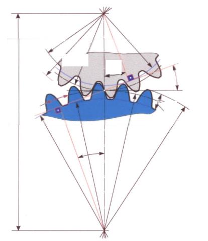
) initial cylinders are replaced by initial cones 1
and 2
. Tooth profiles are approximately considered as the intersection lines of the side surfaces of the teeth with additional cones. 3
and 4,
coaxial initial, but with generators, perpendicular to the generators of the initial cones. The module, initial and pitch circles are measured on an external additional cone. For the convenience of tooth profiling, additional cones are deployed on a plane. 5
and 6.
Involute engagement can be improved by correcting. In addition to involute gearing, clock mechanisms and some other devices use cycloidal gearing, which works with less friction losses and makes it possible to use gear wheels with a small number of teeth, but which does not have the specified advantages of involute gearing. In heavy machines, along with involute gears, circular-wheel gears are used ( rice five
), proposed in the 50s. 20 in. M.L. Novikov. The profiles of the teeth of the wheels in the Novikov engagement are outlined by arcs of circles. The convex teeth of one gear (usually small) are in contact with the concave teeth of the other. The initial touch (without load) occurs at a point. In the transfer Novikov gear wheels helical. The contact points of the teeth do not move along the height of the teeth, but only in the axial direction, i.e. the line of engagement is parallel to the axes of the wheels. The advantages of such freezing systems include: reduced contact stresses, favorable conditions for the formation of an oil wedge, the possibility of using wheels with a small number of teeth, and, consequently, large gear ratios. The bearing capacity of Novikov gears by the criterion of contact strength is significantly higher than the involute ones. For satisfactory operation of the product, their accuracy is necessary. For H. p. Provided 12 degrees of accuracy, selected depending on the purpose and conditions of work of the transmission. The main reasons for a malfunction are: tooth breakage, fatigue chipping of the surface layers of the teeth, abrasive wear, jamming of the teeth (observed when the oil film is destroyed from high pressures or high temperatures). The main materials for gears are alloyed steels subjected to thermal or chemical-thermal treatment: surface hardening, mainly high-frequency currents, bulk hardening, cementation, nitro-cementation, nitration, cyanidation. Z. p. Of steel, improved by heat treatment before cutting teeth, manufactured in the absence of stringent requirements for their dimensions, most often in small-scale and individual production. With special requirements for noiselessness and low loads, one of the gears is made of plastic (PCB, caprolon, laminated plastics, polyformaldehyde), and the mating is made of steel. H. p. Count on the strength of the bending stresses in a dangerous section at the base of the teeth and the contact stresses at the engagement pole. Spare parts are used in the form of simple single-stage gears and in the form of various combinations of several gears, built-in cars or made in the form of separate units. Z. pp is widely used to lower angular velocities and increase torque in Gearbox Oh. Gearboxes are usually performed in separate enclosures of one-, two- and three-stage gear ratios, respectively, 1.6-6.3; 8-40; 45-200. The most common two-stage gearboxes (about 95%). For obtaining different frequencies of rotation of the output shaft at a constant speed of the drive engine, gearboxes are used (See Gearbox). The possibilities of gear mechanisms are expanded with the use of planetary gears (See Planetary gear),
which are used as gearboxes and differential mechanisms (See Differential mechanism). The small dimensions and mass of planetary star gears are determined by the distribution of the load between several gear wheels (satellites) that perform a planetary motion and the use of internal gearing, which has an increased bearing capacity. In the transition from simple gear to planetary, a reduction in mass of 1.5-5 times is achieved. The smallest relative dimensions have wave transmissions (See Wave transmission),
providing the transfer of large loads with high kinematic accuracy and rigidity. Lit .: Kudryavtsev V.N., Gears, M. - L., 1957; Reshetov, N. N., Machine Parts, M., 1963; Chasovnikov, LD, Transfers by meshing, M., 1969; Machine parts. Handbook, ed. N.S. Acherkana, vol. 3, M., 1969. D. N. Reshetov. Fig. 2. Formation of involute profiles: NN - general normal; P - gearing pole; α is the angle of engagement; ω 1 and ω 2 - angular velocities; 1 and 2 - gear wheels. Great Soviet Encyclopedia. - M .: Soviet Encyclopedia.
1969-1978
.
Gear - Gear. Gears: spur wheels; used helical gear; in chevron; g conical. SPEED TRANSMISSION, a mechanism for transmitting rotational movement between shafts and changing rotational speed. Gears can be built into the machine, ... ... Illustrated Encyclopedic Dictionary Transmission using gearing. One of the oldest ways of transferring rotation between shafts, which is widely used today, especially in cases where constant ratios of rotational frequencies are required. Gears ... ... Collier's Encyclopedia gear - transmission Three-link mechanism in which the two moving parts are gear wheels that form a rotational or translational pair with a fixed link. [GOST 16530 83] Transmission Subjects Generalized Terms Terms Related to ... ... Technical Translator's Guide Three-link mechanism in which 2 mobile links are gear wheels (or a wheel and a rack, a worm), which form a rotational or translational pair with a fixed link (body, rack). There are cylindrical gears ... Big Encyclopedic Dictionary GEAR - a three-stage mechanism in which two mobile links are gear wheels (or a wheel and a rack, a worm) that form a rotary or translational pair with a fixed link (body, rack). There are cylindrical cylinders, ... ... Big Polytechnic Encyclopedia Spur gear A spur gear is a mechanism or part of a mechanical gear mechanism that includes gear wheels. Purpose: the transfer of rotational motion between shafts, which may have parallel ... Wikipedia A mechanism for transmitting the rotational movement between the shafts and changing the rotational speed, consisting of gear wheels (either of a gear wheel and a rack) or of a worm and a worm wheel. The links of the simplest single-stage gear rack ... encyclopedic Dictionary The mechanism for transmitting rotate. the movement between the shafts and the change in rotational speed, consisting of gears (either of a gear wheel and slats) or of a worm and a worm wheel. The simplest one-stage 3. p. Consists of a rack, leading and ... ... Big Encyclopedic Polytechnic Dictionary gear - krumpliaratinė perdava statusas T sritis automatika atitikmenys: angl. gear train; gear transmission; gearing vok. Zahnradübersetzung, f; Zahnradgetriebe, n; Zahnradtrieb, m rus. gear train, f pranc. commande par engrenages, f ryšiai: ... ... Automatikos terminų žodynas gear - gear. gear wheel. the gear. gearing. gear pair. worm. worm-gear. hypoid transmission. globoid transfer. planetary gear. helical gear (# gear). chevron (# wheel). gear cutting machine (# machine). gear shaping. ... ... Ideographic dictionary of the Russian language

![]()
Send your good work in the knowledge base is simple. Use the form below.
Similar documents
![]()

See what is the "gear" in other dictionaries: