Ship systems. Ship systems this
Ship systems a set of pipelines, valves, mechanisms, instruments and devices that ensure the movement of the vessel, as well as the receipt and delivery of liquid, steam and gas from the vessel (the systems relating to the ship's power plant are not included in the village system). On purpose S. p. there are: drainage, ballast, fire-fighting, domestic water supply, waste water, heating and domestic steam supply, ventilation and air conditioning, refrigeration, compressed air, etc. In total, there are about 80 ° C on ships. Drive mechanisms (pumps, fans, etc.) S. p. carried out from the auxiliary or main power plants of the vessel or from autonomous drives. Working pressure in pipelines reaches 15-20 Mn / m 2 ,
piping diameters from 3-5 mm up to 1 m and more, the length of the pipelines a few dozen km, power drives mechanisms S. p. exceeds 15 MW S.'s equipment, securing the vessel and protecting the environment from pollution, is regulated by classification societies (See Classification Society) and other organizations that also carry out operational supervision over S. Lit .: Aleksandrov A.V., Ship Systems, L., 1966. L.P. Ivanov.
Great Soviet Encyclopedia. - M .: Soviet Encyclopedia. 1969-1978 .
See what "Ship systems" are in other dictionaries:
The combination of pipelines and fittings, intended. to move liquids and gases on the vessel. S. p. ensure the survivability of the vessel (fire-fighting, drainage, by-pass, and other systems), vessel-wide operational (ballast, dry., ... ... Big Encyclopedic Polytechnic Dictionary
A set of devices, devices and mechanisms for serving the various needs of the vessel during the course and in the parking lot. Devices used to move liquids and gases are allocated particularly to ship systems (see). Mechanisms serving the ... ... Maritime Dictionary
Auxiliary, ensure the operation of the main ship engines (See. Ship engine), ship systems (See Ship systems) and ship devices (See Ship devices). Actually C. m. Include: pumps, compressors and fans, ... ... Great Soviet Encyclopedia
BATCHING SYSTEMS - special ship systems designed to: receive, transfer within the vessel and unload liquid cargo (cargo systems); pumping out of cargo tanks from an unselected liquid cargo cargo system (a stripping system); maintain in tanks ... ...
RESCUE VESSEL SYSTEMS - special ship systems designed to perform a number of special functions on rescue ships: scouring the ground with water jets around a sunken ship or an emergency ship sitting on the ground; suction of soil (sand and silt) from the premises ... ... Marine Encyclopedic Reference
A network of pipelines designed and adapted to move liquids or gases inside the vessel in order to serve its various needs. SS consist of pipelines (highways and shoots), equipped with appropriate valves ... Marine dictionary
ship barge series 1 - (shipbornme barges, series 1): Barges, with which cargo operations are carried out on a carrier ship by a special ship crane, hoist or using a docking system. Source: GOST R ISO 4175 2006: Shipbuilding. Barges ship series 1. ... ... Vocabulary-terms reference terms and technical documentation
Ship Barges Series 2 - (shipborne barge, series 2): barges, the cargo operations with which on the barge carrier are carried out by a lift or using a docking system ... Source: GOST R ISO 7222 2005. Shipbuilding. Barges ship series 2. Main dimensions (approved. Order ... ... Official terminology
Ship Barges Series 3 - (shipborne barge, series 3): barges, cargo operations with which on a barge carrier are carried out using a lift or docking system ... Source: GOST R ISO 6765 2005. Shipbuilding. Barges ship series 3. Main dimensions (approved. Order ... ... Official terminology
Devices to ensure the movement of ships, boats and other vessels. The propellers include the propeller and the paddle wheel. As a ship power plants, steam engines and turbines, gas turbines and ... ... are usually used. Collier's Encyclopedia
Books
- Ship information and measuring systems of fishing fleet. Textbook, Prohorenkov A., Remezovsky V. .. ...
- Ship electrical measuring instruments and information systems. Textbook, S. P. Semenov, A. V. Goreleichenko, E. Yu. Bogachev. The textbook outlines the principle of operation, the basics of the theory, the design and operation of electrical measuring instruments and information systems used in ship electrical power plants.…
The operation of ship systems ensures the survivability of the ship, i.e. safety of navigation, necessary conditions of habitability, safety of cargo, as well as the performance of special functions related to the appointment of the vessel, for example, on tankers, rescuers, fishing vessels.
Share your work on social networks
If this work did not fit you at the bottom of the page there is a list of similar works. You can also use the search button.
MINISTRY OF EDUCATION AND SCIENCE OF UKRAINE
NATIONAL UNIVERSITY
"NIKOLAEVSKY UNIVERSITY OF SHIPBUILDING NAMED AFTER ADMIRAL MAKAROV"
Department of Shipbuilding
ESSAY
with discipline
Ship's ship system
subject: “Fire fighting system of the vessel”
Student _ V _ course _ 5 11 2 groups
Chernyaev Maxim Igorovich
(Prosperity and Inception)
Kervnik
doctor of Technical Sciences Professor_Zaitsev V.V.___
(posada, vchene calling, naukovy stupіn, nickname that ініціали)
Kherson - 2014
Introduction ……………………………………………………………………………… 3
1 General concepts of modern fire-prevention systems ...................... 4
2 Types of fire-fighting systems ………………………………………… ...... 6
2.1 Water fire fighting system …………………………………… ..6
2.2 Sprinkler fire extinguishing system ……………………………… ..8
2.3 Drencher fire extinguishing system ………………………… .. …… ... 10
2.4 Foam fire extinguishing system ……………………………… ........... 11
2.5 Powder fire extinguishing system………………………………..12
2.6 CO2 fire extinguishing system ………………………………………..13
2.7 Aerosol fire extinguishing system .........................14
Conclusion ………………………………………… ... ……………………… ..16
References ……………… ... ……………………… 17.
INTRODUCTION
Ship systems ?? it is a complex of pipelines with valves, their servicing mechanisms,tanks, vehicles, instruments and controls and control over them.
Ship systems are a combination of specialized pipelines with mechanisms, devices, instruments and devices.
They are designed to move fluids, air or gases in order to ensure the normal operation of the vessel (except for the power plant, the pipelines of which are not included in the ship systems).
The operation of ship systems ensures the survivability of the ship, i.e. safety of navigation, necessary conditions of habitability, safety of cargo, as well as the performance of special functions related to the appointment of the vessel, for example, on tankers, rescuers, fishing vessels. On civilian courts usually provide:
- Bilge systems ?? drainage, drainage, overflow, oily bilge water.
- Ballast systems ?? ballast, trim, roll, replacements.
- Fire extinguishing systems ?? water fire extinguishing, water irrigation, sprinkler, water spraying, water curtains, steam extinguishing, foam extinguishing, carbon dioxide extinguishing, volumetric chemical, inert gases, powder extinguishing.
- Domestic water systems ?? fresh household water, drinking water, wash water, domestic outboard water, domestic hot water.
- Wastewater systems ?? sewage, domestic water, scuppers open decks.
- Microclimate systems ?? ventilation, air conditioning, heating (steam, water, air).
- Refrigeration systems ?? refrigerated
- Domestic steam supply systems.
- Compressed air systems.
- Ship equipment cooling systems.
- Hydraulic system.
Auxiliary ?? measuring, air, overflow, communication system, alarm, management.
Special systems:
Tankers ?? cargo, sweep, vapor, wash cargo tanks, irrigation.
Rescuers ?? soil erosion, ground drain, water drainage, compressed gases.
Fishing ?? fish oil, brine, fish feed.
1 General concepts of modern fire protection systems
Modern fire protection systems are based on the use of the latest means and methods of detecting and extinguishing fires and reducing losses from the use of fire extinguishing agents. These include, first of all, the use of water mist and spray water, high expansion foam. All stationary installations of the listed types are designed to extinguish fires in confined spaces.
In modern installations for extinguishing sprinkler fires of a deluge type, the use of irrigators, for example, Aquamaster and similar ones, makes it possible to obtain water extinguishing drops with an average diameter of 100 ?? 150 microns. Not only sprinklers installed vertically, but also with horizontal installation have recently appeared on the market. The water pressure in such installations at the outlet of the sprinkler must be within 0.5 ?? 1.2 MPa (5 ?? 12 kg / m2). The use of water mist allows to reduce the amount of water supplied for extinguishing by 1.5? 2 times and to increase the efficiency of its use.
The use of water spray (superheated water) allows you to extinguish with an average diameter of droplets of about 70 microns and eliminate the fiery burning of almost all combustible materials that do not react with water with the release of a large amount of heat and combustible gases. The time to extinguish the flame of solid combustible materials and liquids, as a rule, does not exceed one minute. The use of installations of this type is hampered by the fact that to obtain water aerosol spray it is necessary either to have a container in which water is constantly at a temperature of 150-170 ° C, or special equipment that allows for a short time to heat the water to the required temperature.
Nowadays, high-multiplicity foam (foam multiplicity of 400 or more) is being used to protect closed volumes. The use of fire extinguishing installations with high-expansion foam allows for a short time to fill the protected volume with foam and eliminate burning. To obtain high-expansion foams, only those frothers should be used, to which the certificate states that they allow to obtain high-expansion foams. The use of such plants can significantly reduce the amount of foaming agent and water stored in the tanks of the pumping station of foam fire extinguishing, and hence the costs.
More and more use of fire monitors with remote control and fire robots. Fire robots in all respects correspond to the automatic fire extinguishing installations: provide automatic fire alarms of the protected area, determine the coordinates of the fire, and automatically extinguish the fire with water spray or low expansion foam. The area protected by one fire-fighting robot ranges from 5,000 to 15,000 m2 with the flow rate of water or frother solution from one barrel from 20 to 60 liters per second ”1.
The most widely used are fire monitors with remote control and scanning guns. They are used for irrigation of supporting structures and farms in the machine rooms of power plants, in the shops of machine-building and other enterprises. Scanning trunks serves a jet of water according to a predetermined program, the mode of water supply (speed and trajectory of the movement of the trunk). Barrels of this type are the cheapest, and in part for this reason their use is much wider. The use of robotic firearms is partly constrained due to their high cost and the need for constant maintenance, which requires the involvement of highly qualified specialists.
The use of fire robots of other types and with the use of other types of fire extinguishing agents is insignificant throughout the world; so, their use is constrained for the same reasons as robotic barrels. But at the same time, it should be expected that the use of fire robots will soon increase with the advent of their new types and designs, as well as lower cost.
For extinguishing fires of petroleum and petroleum products, modern means and methods using low-expansion foam obtained using fluorinated film-forming foaming agents are increasingly used. For extinguishing fires of oil and petroleum products in tanks, the under-layer method of supplying low expansion foam has become quite widespread. However, it should be noted that this method is not applicable to all cases. This method should not be used to extinguish fires of flammable liquids with high viscosity, as well as polar liquids that destroy the supplied foam at high speed. It is problematic to extinguish high-octane gasolines by the underlayer method, in which the content of polar liquids reaches 18 ± 20%. To extinguish fires of polar liquids and mixed fuels should be applied to the supply of low expansion foam from the top using foaming agents designed for this purpose.
To extinguish fires in tanks equipped with a pontoon, you should use the combined method of supplying low expansion foam to the tank. In this method, the foam is supplied to the surface of the flammable liquid and under the layer of flammable liquid at the same time. The use of this method of supplying foam allows you to eliminate burning in almost all cases, including those when the pontoon is in the lower position, for example, when the tank is taken out of service for repair work.
2 Types of fire protection systems
Stationary fire extinguishing systems are mounted during the construction of the vessel. They are divided intolinear and annular . Stationary installations allow you to quickly apply a fire extinguishing agent to the fire, take it under control and ensure the extinguishing.
2.1 Water extinguishing system ?? The main system to protect is equipped regardless of the presence of other systems. The pipeline system consists of a main line with a pipe diameter of 100-150 mm and branches with a diameter of 38-64 mm. All sections of the water-burning line passing through the open decks should have drain valves for draining the line in case of a dangerous drop in temperature.
Water fire fighting system (VPSA is designed for:
- provision of high pressure overboard water to consumers of the complex of the system of the struggle for survivability (HLB) - irrigation and water-spraying systems, protection systems for watches and gatherings;
- provision of high-pressure seawater as working water for ejectors of the drainage system of the holds;
- providing the seawater with the seawater system intended for servicing the washing system during l / s sanitary treatment and servicing of the washout in the latrines.
VPSA performed byring pattern (see picture) with seven combat jumpers and consists of:
Picture 1 ?? Water Fire System Diagram
- three TPZhN-150/10 turbopumps with a capacity of 150 cubic meters / hour and a pressure of 10 m.vod.st located in the fore machine-boiler department (MKO), the auxiliary boiler (PLC) and the stern MKO and serving for supplying outboard water to jumpers number 3, 4 and 5;
- four NTsV-160/80 electric pumps with a capacity of 160 cubic meters / hour and a pressure of 80 m.v.st. located in pairs in pump rooms Nos. 1 and 2 and serving to supply seawater into battle jumpers Nos. 1, 2, 6 and 7;
- seven combat jumpers, each of which is connected to one fire pump. Water is taken to the consumers mentioned above ONLY from jumpers;
- eighteen main disconnecting valves with remote control from the post of energy and survivability (PEL) with the help of electric actuators, which serve to disconnect VPSS in combat mode and switch sections of VPSS to supply water to other jumpers when any pumps or sections of the system fail. These valves are labeled with an exclamation mark;
- remote monitoring and control systems, consisting of local control gauges located at the pumps, remote gauges located on the mnemonic circuit in the CLE and spare CRL (remote control KMKO), as well as pressure sensors connected to each jumper and serving to automatically start the standby electric fire pump when a drop in pressure in the UPPS to 6 kgf / sq. cm in everyday mode. In addition, the system of remote control and control includes the control gear of electric fire pumps.
VPS works in two modes:
- battle mode - in this mode, all the main isolating valves are CLOSED and ALL seven pumps are working. At the same time, autonomous power supply of jumpers with their consumers is provided. When the pump servicing the jumper fails and any onboard branch of the “ring” is in good condition by switching the corresponding valves, the non-operating jumper is connected to the operating ones.
- daily routine - in this mode at the parking lot TPGN No. 2 is in operation, TPGN No. 1 and 3 are on the move. All electropumps that are not in scheduled preventive inspection or repair (PPO and PPR) are on duty - ready for automatic start when the pressure drops in the UPPS up to 6 kgf / sq. cm.
The normal value of pressure in the UPPS is 7-8 kgf / sq. Cm.
In general, this design performance of the UPPS is considered to be the classic and most reliable even in comparison with the execution of a similar system on ships of later projects. The strongest points of this solution are:
- very short jumpers located across the hull of the ship (minimizing the amount of potential critical damage);
- availability of three turbo fire pumps. Based on the concept of ensuring the efficiency of the steam power power plant (CSP) in the absence of electricity on the ship (full self-maintenance), the water supply to the UPPS will also occur despite the absence of electricity.
The weak point of the constructive solution is the low location of the jumpers and the onboard branches of the “ring”, that is, the jumpers together with the taps to the consumers fall into the target volume during underwater explosions. When the jumpers are located near or at the level of the unsinkable deck (lower deck), this deficiency could be eliminated.
2.2 Sprinkler fire extinguishing systems used on ferries and passenger ships to protect the living quarters, adjacent corridors and public spaces. Their purpose ?? in limiting the spread of fire and reducing the temperature in the protected premises, which makes it possible to organize a reliable evacuation of passengers and crew members.
In all protected areas establish a sufficient number of sprinklers ?? special valves with fusible inserts, ensuring the closed position of the valves. When the temperature in the premises rises, the low-melting insert melts, the sprinkler valve opens, and water begins to spray around the room. On ships, sprinklers are usually used, triggered at a temperature of 60-75 ° C;
Legend: 1 - Distribution pipeline; 2- Universal pressure signaling device; 3-Shield control and monitoring; 4- Pneumatic bag or impulse device; 5- Control and starting node; 6 ?? Normal shutter; 7 ?? Electric motor; eight ?? Pump; 9 ?? Fire alarm station; ten ?? Compressor.
Figure 2 ?? Scheme sprinkler installation fire extinguishing
2.3 Drencher fire extinguishing system on the layout of the lines and the installation of spray heads is similar to the sprinkler. Pipelines in their normal state are not filled with water. When the system is turned on, the pump starts up and supplies the seawater to the main line to all sprayers ?? fine water covers the protected area. Fire extinguishing systems
used to irrigate the cargo deck of ships with horizontal loading and tankers, pipelines and open surfaces of gas carriers. In case of fire, the drencher plant cools the metal decks and other ship structures, preventing the spread of fire.Drencher plants are designed to simultaneously extinguish a fire across the entire protected area, create water curtains, and irrigate building structures, tanks with petroleum products and process equipment.
Drencher installation may consist of one or several sections. Each of them is serviced by an independent control and starting node. Automatic activation of drencher installations can be provided by one of the following incentive systems:
- in the presence of the valve group action ?? a hydraulic or pneumatic system with sprinklers, a fire alarm system and a motive pipeline, a cable system with fusible locks;
- in the presence of valves and valves with electric actuator ?? fire alarm system with electric fire detectors.
2.4 Foam extinguishing systemit is used in case of fires in machine rooms and pump rooms. All tankers are equipped with deck installations of foam fire extinguishing.
On ships recommended installation of air-mechanical foam.
Legend: 1 ?? Automatic water feeder (Pnevmobak); 2- Pipe-wire from the main water feeder; 3-tank with frother; 4- Distribution water supply; 5- Locking device; 6 ?? Foam sprinkler; 7 ?? Alarm device; eight ?? Control and start-up node.
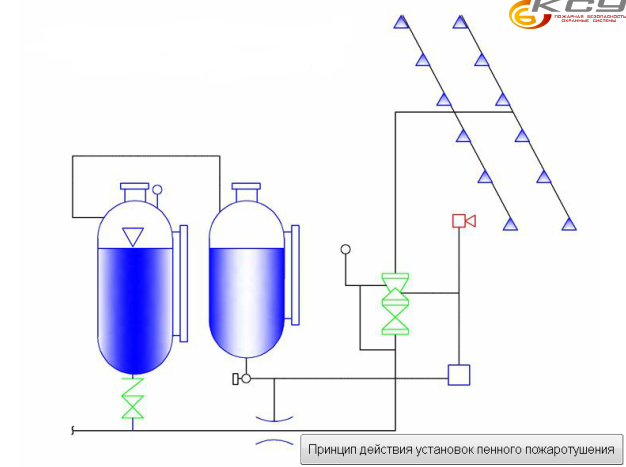
Figure 3 ?? Scheme of foam sprinkler fire extinguishing
2.5 Powder Fire Extinguishing Systemsall vessels carrying liquefied gases in bulk should be equipped. On the vessel there may be several installations mounted on a sled so that the areas they protect overlap each other.
Foam as a fire extinguishing agent has a high insulating property and partially cooling. With the introduction of the installation in the mixer begin to supply water and a foaming agent. The foam solution formed in the mixer goes to the fire. At the exit of the foam solution, air ejectors are installed, in which the pricing process is completed due to air leaks.
The duration of the installation depends on the amount of foaming agent in the tank. When all the foaming agent has been used up and water begins to flow through the outlet openings, the installation is turned off in order to avoid destruction of the foam. An important word for fire suppression is maximum foam flow during the first 3 minutes. Stationary fire suppression trunks are located so
so that any point of the protected space was removed no more than 9 m.
By the method of controlling the installation of powder extinguishing powder are divided into:
- Automatic installation ?? Fire detection is carried out through the installation of an automatic fire alarm with the subsequent receipt of a signal to start AUPPT.
- Installations with manual start (local, remote) ?? the signal for the start of the AUPPT is sent manually from the fire station, fire extinguishing station, protected premises.
Standalone installation ?? Fire detection and powder composition functions are carried out independently of external power sources and controls (as a rule, fire extinguishing modules are equipped with this function to increase the reliability of operation when external systems fail).
Legend: 1 ?? Fire extinguisher housing; 2- pneumatic valve; 3-cylinder with compressed gas; 4-Guide tube with a load; 5-tross; 6 ?? Manual start handle; 7 ?? Fusible lock; eight ?? Nozzles
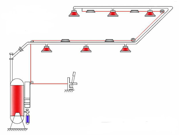
Figure 3 ?? Scheme of automatic powder fire extinguisher.
2.6 CO2-extinguishing systemused to protect cargo, engine and pump rooms, storerooms, galley. Stationary CO2-fire extinguishing installations equip machine and
cargo spaces of the vessel. The installation of C02 fire extinguishing machine rooms is put into effect if previously taken measures did not allow to localize the fire. On the main line, carbon dioxide gas is supplied in the liquid phase under pressure, expands at the outlet, and dense gas is fed into the fire zone, effectively displacing oxygen and reducing its content in the air to 15% or less. Carbon dioxide as a fire extinguishing agent is neutral and does not damage expensive goods and mechanisms.
Before putting the CO2-extinguishing installation into operation, the protected room must be sealed, 20 seconds before the gas is supplied, an automatic alarm is activated, at the same time the light panel lights up, warning people about the danger. At the alarm, all people must leave the premises. The senior mechanic is obliged to ensure the evacuation of people from the engine room. Without a breathing apparatus, it is dangerous to enter a room where carbon dioxide has been supplied, even for a short time.
2.7 Aerosol extinguishing systems designed to eliminate indoor fires associated with the use of flammable liquids in the holds of ships, art galleries, museums, archives, cable tunnels, on various electrical installations under voltage, as well as in all cases where the properties of substances and materials involved in combustion do not allow to use water or air-mechanical foam for fire fighting, or when using gas fire extinguishing installations gives a greater economic effect. Gas extinguishing installations are divided: by the method of extinguishing, by the method of start-up and by the method of storage of the extinguishing agent.
According to the method of extinguishing, these installations are divided into installations of surround and local fire extinguishing. The method of volumetric extinguishing is based on the uniform distribution of the extinguishing agent and the creation of fire extinguishing concentration in the entire volume of the room, which ensures effective extinguishing at any point of the room, including difficult to reach. Volumetric extinguishing installations are used in enclosed spaces where rapid fire development is possible. Installations of local (local) extinguishing are used to extinguish fires of units and equipment in case of impossibility or inexpediency of extinguishing in the volume of the whole room. The principle of local fire extinguishing is to create a fire extinguishing concentration in a dangerous spatial area of the room. Local extinguishing can be carried out using automatic installations or by manual means.
By way of starting the gas extinguishing installation are:
- with cable (mechanical);
- pneumatic;
- electric;
- combined start.
According to the method of storage of extinguishing agents in cylinders installation is divided into the installation:
- under pressure;
- without pressure.
Legend: 1- Automatic start disconnection unit; 2-Motive pipe; 3 Incentive cylinders; 4-valve switchgear; 5-pressure indicator; 6 ?? Graduation nozzles; 7 ?? Nozzles incentive system (spreeklera); eight ?? Manual faucet; 9 ??Stop valve ; ten ?? Sectional y fuse; 11-start air cylinders; 12-Cylinders with fire extinguishing agent.
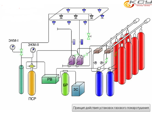
Figure 5 ?? Scheme of gas fire extinguishing system.
Conclusion
In recent years, in Ukraine, reconstruction, capital repairs and technical re-equipment of industrial and public buildings at various facilities are being carried out at a high rate. This also applies to water transport facilities. In large, medium and even small cities where there are reservoirs (river, sea, lake) for the arrangement of hotels, restaurants, office premises use the vessel. For these purposes, use of parking, passenger, permanently or temporarily exploited at the pier (shore), as well as decommissioned vessel.
Fire safety on shipsis extremely important. Vessels are autonomous, their premises with varying degrees of fire danger are located nearby, there are combustible materials in their structures, there are sources of ignition in the rooms, and escape routes are limited. These factors increase the fire hazard of ships. In this regard, the issues of ensuring the safety of people in case of accidents or fires on ships is particularly relevant.
Ships are designed and built according to special rules, unlike buildings and structures. The safety standards in these rules are constantly being improved in the light of international experience. In Ukraine, the classification of civilian courts and their technical supervision is carried out by the national classification society - the Shipping Register of Ukraine. According to the Rules of the Shipping Register of Ukraine, “parking vessels are non-self-propelled floating structures with a pontoon-type hull or a vessel of education, which are usually operated at the pier (shore).” The fact that the ship has a valid Register class means that it is under the supervision of its technical condition, as provided for in the Rules of the Classification Society. According to the operating conditions and the class symbol, the vessel must fully or to a certain extent comply with the requirements of the Regulations that apply to it for the intended purpose. The Register Rules contain requirements forfire safety on ships, namely to the structural elements of the fire protection of the vessel, fire extinguishing systems and fire alarm systems, as well as fire-fighting equipment and support.
References
2. http://sea-library.ru/bezopasnost-plavanija/196-uglekislotnoe-pozharotuschenie.html
3. http://www.ooo-ksu.ru/pozharotushenie.html
4. http://admiral-umashev.narod.ru/ttd_14.html
5. http://www.engineerclub.ru/sistemi13.html
6. http://www.glossary.ru/cgi-bin/gl_sch2.cgi?RRzkui:l!xoxyls: [email protected]
7. http://ksbsecurity.com/protivopozharnye-sistemy/
8. http://crew-help.com.ua/stati_out.php?id=58&tema=an
9. http://bibliofond.ru/view.aspx?id=51665
10. http://seaspirit.ru/shipbuilding/ustrojstvo-sudna/sudovye-sistemy.html
11. Chinyaev I.A. Ship systems
M .: Transport, 1984, 216c. 3rd edition revised and enlarged.
12. Aleksandrov A.V. Ship systems
Edited by Voitkunsky Ya. I. - L .: Shipbuilding, 1985. ?? 544 s.
10
Other related work that might interest you. All\u003e |
|||
| 3704. | Fundamentals of ship theory | 1.88 MB | |
| Allowance for self-study Stability of the marine vessel Ishmael ?? 2012 Handbook on the Basics of Ship Theory Course developed by Dombrovsky V. Chimshyr, Senior Lecturer, SViES Department. The Handbook deals with the monitoring and ensuring the stability of sea vessels and presents a list of issues addressed by the navigator to maintain the vessel in the nautical state and brief explanations on each issue. In the annexes, the materials of the manual are set out in the sequence necessary for an understanding of students of the Basics of Theory of Ship theory. | |||
| 15302. | THEORY AND DEVICE SHIP | 99.52 KB | |
| The main technical and operational characteristics of the vessel. Vessel class Register of Ukraine. Determination of the displacement of the coordinates of the center of gravity and the landing of the vessel. | |||
| 14893. | Determining the location of the vessel by two bearings | 322.02 KB | |
| Determining the location of the vessel by two bearings. Put on the track line the number of the vessel at the time of taking the bearings. At the point of their intersection, we obtain an observable place of the vessel at the time of taking the bearings. The following factors affect the accuracy of the location: the direction of direction finding; vessel speed; systematic error error in the amendment of the compass. | |||
| 14892. | Determining the location of the vessel in two horizontal corners | 215.78 KB | |
| Determining the location of the vessel in two horizontal angles. Measure the three angles between the directions on three landmarks according to the scheme as shown in the figure below. To fix the time T and the counting of the lag of the OL measuring the second angle. Two measurements of the first angle to average ... | |||
| 14891. | Basics of determining the location of the vessel by the method of observation | 293.02 KB | |
| Basics of determining the location of the vessel by the method of observation. Determining the vessel’s position only by the numbering method does not meet the safety requirements of navigation. The numbering errors accumulate and the accuracy of the ship’s position decreases in proportion to the distance covered in the calculation. Observation is the determination of the vessel’s position from measurements of navigation parameters of navigation landmarks with known coordinates. | |||
| 1476. | CALCULATION OF CENTRIFUGAL PUMP OF CONDENSATE SYSTEM OF THE SHIP | 287.64 KB | |
| The condensate-feed system is designed to remove condensate from the main and auxiliary condensers, receive and dispense, store, prepare and supply feed water to steam generating plants and units and to control regulators. | |||
| 17692. | Development of principal technology for the construction of the hull | 269.83 KB | |
| The dimensions of the 96x34x12 workshop and the number of spans 1 create difficulties for workers both in assembling and welding sections and in the specialization of each span. One span complicates the task of placing on the production area of working areas for the formation of embedded flat bottom deck side and curvilinear bow aft sections; - due to the increase in the number of spans, an increase in the number of ... | |||
| 20558. | Development of technology for the manufacture of welded metal structures "Section of the flooring of a refrigerator vessel" | 1.34 MB | |
| Welding applications are continuously expanding. Welding has become a leading technological process in the manufacture and repair of metal structures and products in the industry, construction, transport, agriculture, etc. Some are just learning about their potential and are still being learned and their main use in the future. | |||
| 20574. | SHTURMAN PROCESSING OF THE CF-7200A-1 PROJECT SHIP'S ROUTE OF THE PROJECT ON THE ROUTE OF SAINT-PETERSBURG - KALININGRAD | 413.88 KB | |
| Writing an explanatory note and presentation to the head for review. Analysis of requirements for the current state of nautical charts manuals and manuals for navigation. Description of the procedure for completing the vessel with maps and aids for navigation. Selection of maps of manuals manuals for swimming. | |||
| 4138. | The system of alternative voting. The system of cumulative voting. Bali system | 4.28 KB | |
| The system of alternative voting. The system of cumulative voting. The system of balances The method of unacceptable inefficiency of the system absolutely absolutely vse u pershuyu turi viborіv голос alternatively not voting preferential or absolutely voting for one vibrational voting for one candidate aly v prokuyut with the order of your vocation for you as an alternative vibro for voting one choice ale of one way for your own vocational training Such a system has been procured in Australia in the case of choices of the Palati of representatives of the lower chamber of the Australian Parliament. | |||
Ship power plant - a set of mechanisms installed on the ship serving for the conversion of thermal energy into mechanical energy when burning fuel and for vessel movement, cargo operations and other ship needs, for rotation of propulsion, propellers, paddle wheels. The SSU consists of main engines and auxiliary mechanisms: pumps, compressors, generators, etc. The vessel having an internal combustion engine is called a steam-ship. Auxiliary engine provides power generation.
Classification of shipboard SS: By location (Suspended, stationary), By engine type (piston, gas turbine, steam piston, steam turbines, thermonuclear) Propulsion - a device for converting engine energy or natural source of energy into energy that drives the vessel. Classification of propulsion: oar; sailing; wheel; screw; jet; reactive.
8.Ship devices. Designation of ship devices.
Steering, anchor, mooring, towing, coupling, boat, cargo device.
Steering device consists of: steering, rudder, steering gear, steering gear steering machine [email protected]
The rudder consists of a feather and a puller rigidly bonded with it. A pen one or several plates of a streamlined shape. The shape of the cross-section distinguish between flat (small self-propelled and non-self-propelled vessels) and streamlined rudders.
Types of rudders: the balancing @ -wire of the puller passes in the region of the center of hydrodynamic pressure, i.e. The puller is installed at some distance from the nose edge of the steering wheel. The semi-balancer @ -wire of the puller passes between the leading edge and the center of hydrodynamic pressure.
Steering machines: manual-used on small vessels as the main and installed in the wheelhouse; electric-installed in the tiller compartment; electro-small, smooth and quiet operation; steam.
The steering actuator transmits efforts from the steering car to the baller hands. It includes: sector, cable traction. The sector is called the tiller.
Boat device serves to connect the vessel with the shore, as well as to rescue the team in emergency situations. It consists of a boat, davits with winches, sloops, rostr-blocks and fixtures fixing boats in a marching way.
Lifeboat-workers and rescue.
Keel blocks for keeping boats on deck.
The davits are a device for lifting and lowering a boat. The davit designs allow you to raise and lower boats with people and snob.
Cargo device designed for the production of loading and unloading, when there is no coastal crane equipment. The cargo device includes ship cranes, cargo booms and bilge hoists of various designs.
Load capacity 300-600t.
Signaling tools: sound (beep), siren, smoke bombs and so on.
9. Ship systems. Appointment of ship systems.
Each ship system consists of:
The pipeline network to move through them the appropriate environment
Compensators in long pipelines
Valves for controlling the movement of the medium
Mechanisms: pumps, fans, compressors, devices for changing the state of the transported medium
Sensors of various kinds
Tanks, cylinders, tanks for the storage of liquids and gases.
According to the principle of management ship systems are divided into:
The centralized system is serviced by 1 or a group of pumps located in the engine room;
Autonomous — meanism serves only 1 of the ship’s compartments;
Group-mechanism serves a group of compartments;
Decentralized — all consumers are served by a single pump through a common trunk pipeline.
The purpose and nature of the functions performed ship systems are divided into groups: bilge, sanitary, fire, artificial microclimate, special systems of tankers.
Bilge system. It includes:
Ballast. Serves for receiving or pumping water from the ballast compartments in order to change the trim of the vessel. It is used for empty runs. The magnitude of water ballast can reach 20-40% of the vessel's carrying capacity.
Differential or roll systems. Icebreakers are mainly equipped for it; for rocking the vessel by transferring ballast from tanks of the 1st side to tanks of the opposite or from the bow compartments to the stern compartments and back.
Drainage. It serves to remove water accumulating under the slander of the engine room and holds. The water should be removed into special containers located in the hull of the vessel
Vodootlivnaya. Serves for siphoning large masses of water when receiving holes. With such a system usually rescue ships are equipped.
Sanitary system.
Water supply system - preparation and supply of drinking and outboard water to places of consumption; consists of tanks for storing supplies of drinking water, a piping system that supplies water to the cabins and service rooms, as well as pumps and devices that maintain pressure.
Waste paper is used to collect and remove waste and phycal waters.
Shpigatov-removal from the deck of water during cleaning or rain.
Fire protection system.
Fire alarm-detection of the fire. On ships of the isp system: water-extinguishing; steam-steaming; chemical extinguishing agent or mechanical foam; carbon dioxide extinguishing system-for the prevention of fires on oil-filled vessels and the system of filling in compartments with inert gases.
Artificial microclimate system.
Heating, ventilation, air conditioning system, re-sectioned and special. The heating system should provide the air temperature in the room 18-20 degrees.
Special tanker systems.
On oil provide:
gruzovaya.pozvolyaet osusch unloading of oil products on its own.
sweep. refers to the cargo, but has less performance.
heating. serves to heat cargo for cargo operations.
gas-removal of oil product vapors from cargo tanks into the atmosphere.
The cargo tank cleaning system serves to remove the residue of petroleum products adhering to the set and skin inside the tanks.
10. Radio navigation equipment. Types of rooms on the ship.
Radio navigation equipment can be divided by function:
Informing about external conditions: wind signs, echo sounders, logs
Informing about the position of the vessel in relation to the land and about the position of other vessels in relation to the vessel: radar, thermal imagers, GPS navigators, chartplotters
Communication means allowing to receive and transmit information, both in manual and automatic mode: walkie-talkie, weather stations, rescue beacons.
Autopilot
The main means of external communication is radio communication. Radio communication is carried out in the modes of telephony, digital selective calling, direct printing. The satellite communications system provides seafarers with direct automatic dialing, telex, fax, e-mail, data transfer mode. Special communication systems provide for the transfer of information to ships to ensure the safety of navigation.
Since 1999, the Global Marine Maritime Distress and Safety System (GMDSS) radio equipment has been installed on all ships. The main purpose of the GMDSS is the operational organization of the search and rescue operation of an emergency vessel by the coastal rescue coordination center (SCC) with the involvement of vessels and other assets located in the disaster area.
Ship's premises are formed by dividing the ship's hull into compartments and dividing compartments, superstructures and chopping by decks, platforms and enclosures into separate confined spaces. The number and location of ship premises, their equipment and size are determined by many factors. According to the Rules, ship premises are divided into control stations, residential, office, cargo, engine rooms, storage of fuel and lubricating oils, pumping, production facilities, rooms of a special category. Management posts. The ship control post is located on the navigating bridge indoors in the wheelhouse, which has two exits - one for each wing of the navigating bridge - and the passage from side to side.
Ship system - This is a complex of shipboard equipment, consisting of pipelines, mechanisms, devices, instruments and devices, designed for different kinds of consumers, performing one sludge several functions to ensure the normal operation of the vessel.
The overall goal of technical operation of ship systems, along with ensuring the safe and reliable operation of the vessel, is the effective fulfillment of its transport purpose.
The following general requirements are imposed on ship systems: high safety, reliability in rolling, pitch and roll, economy, environmental friendliness, full automation, and particular requirements:: compliance with the vibration and noise characteristics of valves and pipelines, low hydraulic resistance, sufficient shock resistance, tightness, elimination of losses working environment in the surrounding space. Particular requirements largely depend on the method of controlling the fittings, the material of the pipes and fittings, the type of insulation, the location and method of location in various rooms, etc.
Purpose of ship systems:
- supply and preparation of fuel, lubricating oil, cooling water,; pressed air, removal of exhaust gases of heat engines;
- ensuring the safety of the vessel’s navigation in various navigational conditions with the help of bilge systems: drainage, ballast, sewage, drainage;
- ensuring the normal living conditions of the crew and the safety of passengers, the so-called household systems (drinking water supply, washing and outboard water), sanitary (fecal and waste water systems), heating, ventilation and air conditioning;
- Ensuring the environmental cleanliness of the environment as a result of the operation of the vessel and its technical means with the help of a bilge and oily water purification system, a plant for the treatment of waste and household water, incinerators (incinerators), a system for cleaning exhaust gases from NOx and C02;
- performance of cargo technological operations and ensuring the safety of the vessel and cargo through the use of special systems on bulk vessels (tankers, chemical tankers, gas carriers): cargo, stripping, washing tanks, heating, gas exhaust systems, inert gas systems, etc.);
- ensuring the fire safety of the vessel with the help of fire extinguishing systems (water extinguishing systems: steam extinguishing, carbon dioxide extinguishing, foam extinguishing, liquid extinguishing, extinguishing with inert gases).
Ship personnel need to be well aware of not only the design of all ship systems, but also the safe rules, as well as the best practices for their technical operation.
The ship system has the following elements:
- the source of the working environment (tanks, tanks, cylinders, tanks and other containers);
- a source of energy that provides movement of the working environment (pumps, compressors, fans);
- devices and devices for processing the working environment, which ensure the change and bringing the parameters of the working environment to the required values (heaters, coolers, condensers, steam traps, steam generators, filters, separators, etc.);
- instrumentation (instrumentation): pressure gauges, thermometers, level gauges, flow meters, gas analyzers, viscometers, hygrometers, automatic control devices, alarms, protection and diagnostics;
- consumers of the working environment (hydraulic and pneumatic drives, servomotors, etc.);
- pipelines that combine these elements into the system. The ship system may have a different combination of these elements.
There are systems in which some of the listed elements may be missing.
The main element of any system is the pipeline. The movement of liquids and gases through pipes occurs due to the message of mechanical, thermal, potential energy. Therefore, any system consists in coarse, connecting mechanisms, devices and fittings of various purposes and designs.
By function, the individual pipelines are divided into the following types:
- reception;
- pressure head;
- bulk, in which the liquid passes by gravity into the vessel's tanks or under pressure from the onshore pump;
- the drain, in which the liquid is supplied by the ship's pump from the premises and holds overboard;
- bleed, in which the liquid or gas passes when the safety valves are triggered;
- blowing through which the liquid is removed to the hold or to the vessel’s tanks, usually condensate or steam-water mixture;
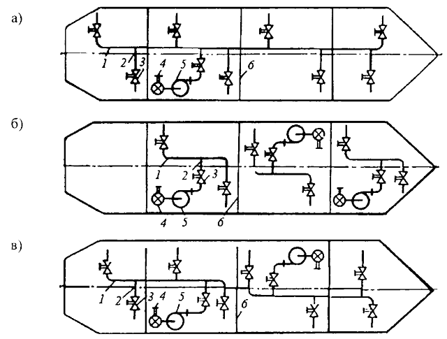
Fig. 1.1. Principal diagrams of trunk systems: a - linear; b - ring; in - combined: / - linear highway; 2 - pipeline consumers a separate compartment; 3 - pump; 4 - drain pipe; 5 - cast Kingston; 6 - disconnecting valve; 7 - ring highway; 8 - jumper
- air, which is designed to communicate with the atmosphere;
- exhaust (usually in the ship ventilation system).
By the nature of the medium flowing through the pipelines, apply water pipes, steam lines, air ducts, brine pipelines, gas pipelines, oil pipelines, oil lines, fuel lines.
The principle of construction of the ship system depends on the type of vessel, its displacement, destination, requirements for operation and survivability.
There is the following classification of ship systems:
- by purpose and nature of the operations: vessel-wide, domestic (bilge, drainage, ballast, sanitary, fire-fighting, heating, ventilation) and special;
- according to the concept - linear, ring and combined lines (Fig. 1.1);
By way of building the system: centralized, autonomous or group (Fig. 1.2).
Let us consider the classification of ship systems.
The linear scheme of the system is a pipe line laid along the vessel. It is the simplest and is therefore used in most ship systems.
The annular circuit consists of two pipelines laid along the vessel on both sides, and several jumpers on which the isolating valves are installed. The use of a ring circuit improves the survivability and maneuverability of the system, since in the event of a pipeline failure on one side, another pipeline may function. However, this scheme requires an increase in the length of pipes and the number of valves, which entails an increase in the mass and cost of the system.
The combined circuit consists of several interconnected linear and circular highways. Sections of the common highway, which should have a high survivability, perform in a ring pattern, the rest - in a linear. Combined line, combining the advantages of linear and ring lines, used mainly on large ships. Pipelines are divided into a number of sections by installing disconnecting valves in order to disconnect the damaged section from the entire highway. The highway is laid under the floorings and platforms, shifting to the longitudinal bulkheads in the corridors and aisles, so as not to clutter residential and office premises and have access in case of equipment repair. To avoid freezing, water piping is located below deck. Provides for the possibility of the descent of water with drain plugs and faucets.
With a centralized scheme, there is a minimum number of mechanisms and fittings, which creates simplicity and convenience in its maintenance.
In the autonomous scheme, it is provided for the consumers of this compartment to be serviced by an independent mechanism and a separate pipeline. According to this principle, drainage, ballast, cargo and other systems are built. The autonomous principle is applied to individual compartments that are of particular importance for the entire vessel, as it ensures maximum survivability of the system (for example, when one compartment is flooded, the system completely provides consumers of all other compartments). The disadvantage of it is that the system is bulky, with a large number of mechanisms and fittings having a low utilization factor.
In a group scheme, the ship’s compartments are divided into groups served by a single mechanism and an independent pipeline. The group scheme in its advantages and disadvantages takes an intermediate place between the first two. According to the group principle, ventilation, heating, air conditioning and waste systems are built.
By the principle of moving the pumped medium, the systems are divided into the following types:
- closed systems, which exclude contact of the working environment with the atmosphere;
- open systems in which there is constant contact with the atmosphere;
- flow systems that use outside water and atmospheric air that are removed into the surrounding space;
- circulation systems in which forced or natural circulation is organized or repeated use of the working environment under pressure with a limited supply of working environment.
Hydraulic system.
General information. The hydraulic system transfers energy (hydraulic fluid) through pipes through a pump to the hydraulic motor (hydraulic motor), which drives the mechanism.
The scheme of the classical hydraulic system:
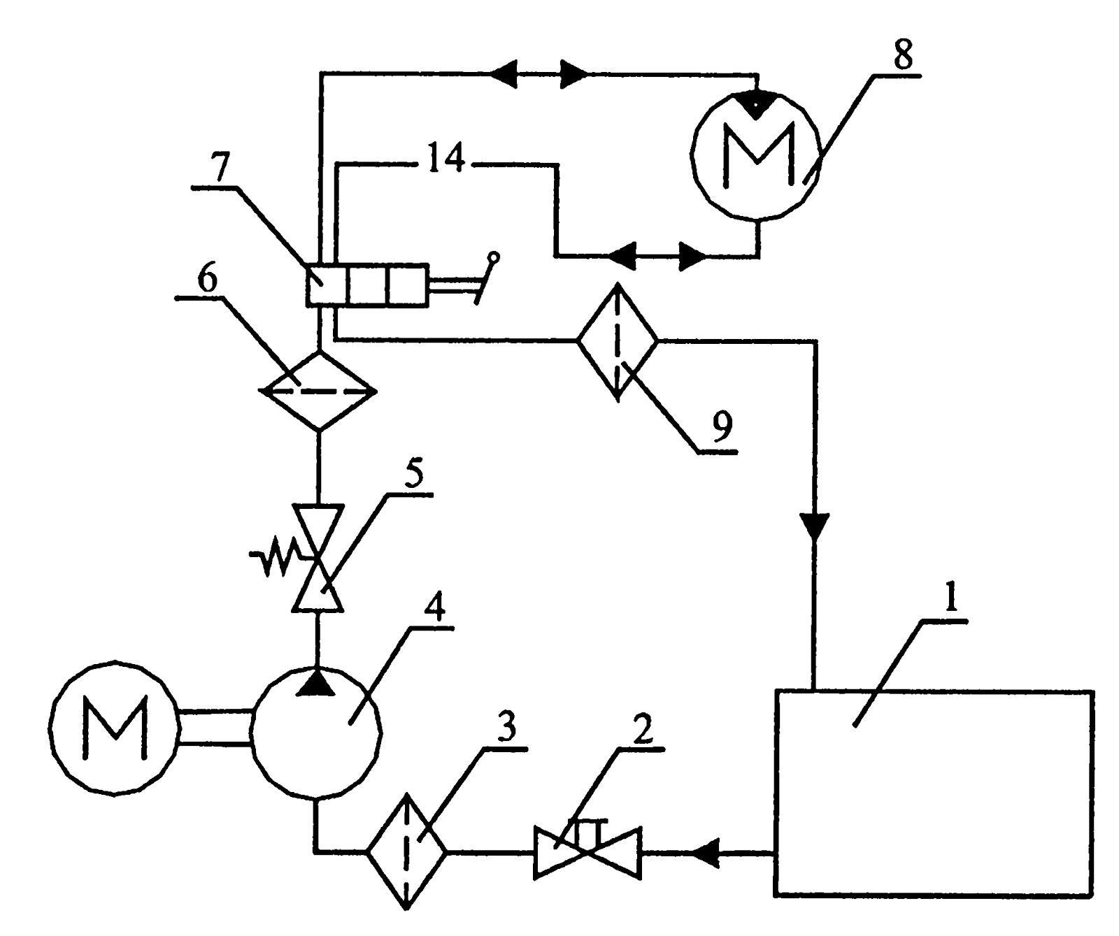
1 - hydraulic tank; 2 - stop valve; 3 - filter; 4 - electric pump with constant performance and constant direction of fluid flow; 5 - safety valve; 6 - filter; 7 - valve with local manual control of the handle; 8 - hydraulic engine; 9 - filter.
By design, the pump and hydraulic motor can be radial and axial-piston, lamellar, gear and screw.
On vessels of commercial and marine fleets, the hydraulic system is used to drive and control steering gear, pitifulators, CPP, for cargo, towing and warping winches, cranks and spiers, hatch covers mechanisms, ramps and hydraulic lifts.
Maintenance. During the operation of the hydraulic system, it is necessary to perform maintenance in the following volume:
- clean the filters after 50, 100 and 500 hours of operation. If metal chips are detected in the filters, it is necessary to check them more often. With the reappearance of metal shavings, it is necessary to identify the source of its formation and eliminate malfunctions;
- monitor oil leaks through seals and hydraulic pipe connections. In the event of leaks through the seals or connections, they must be replaced (in the connection should be replaced gaskets). It should be remembered that the replacement of seals and gaskets, as well as pulling connections under pressure is prohibited;
- periodically check the level of fluid in the tank. In the case of reducing it to replenish the tank to the working level;
- once in 3 months it is necessary to control the quality of the working fluid. The simplest method of control — using a glass filing cabinet — places sediment after filters on glass plates, and a tag with the number and month of sampling is attached to the back side. The plates are stored in a special box. A set of plates allows you to visually monitor the status of the working fluid. Glass can be replaced with laboratory beakers;
- change the working fluid after 2 thousand hours of operation, or once every two years. When changing the fluid, the hydraulic tank is cleaned and the pipelines are washed.
Care must be taken to ensure that the space above the normal level of oil is thoroughly rinsed and pickled, since it is particularly susceptible to the process of rusting and pollution. After cleaning, the internal cavity of the tank should be treated with an oil-resistant paint of the type of sealant GE Dlyptol Red, which is used according to the manufacturer's instructions.
Keep the system clean. Dirt is the most common cause of system failures.
Flaw Detection and Repair. When a hydraulic system fails, first of all you need to check the fluid level in the system, as well as its quality. After monitoring, check the pump parameters by short-term start-up. If the pump pressure is normal, in the future you can go to check the operation of the actuators, alternately turning them into operation.
When a knock or a sharp sound appears, it is necessary to stop the pump or hydraulic motor that produces a knock or sound, visually check all external connections, thrust, dampers, fasteners and springs. Then you should check the system lock and alarm.
Before repairing the hydraulic system, it is necessary to carry out control tests in order to identify faults. It is recommended to repair the entire hydraulic system. Sometimes, in order to save, individual hydromechanisms are handed over for repairs, not including pipelines and valves. This practice of single repair does not justify itself, since not only failed hydraulic mechanisms, but also working ones can serve as sources of contamination of the working fluid. Therefore, after assembling the repaired mechanism, but without a complete reassembly of all hydraulic system elements, without replacing all rubber cuffs and seals, and also without flushing the system, it will not work for a long time.
Repair of the hydraulic system in the conditions of the vessel is possible only in terms of assembly, disassembly, replacement of the cuffs and seals with a single set of spare parts and accessories. With this repair it is impossible to achieve the required cleanliness of rubbing surfaces.
Most failures, as well as reduced performance of all hydraulic systems, occur due to the presence of contaminants in the working fluid (water, various mechanical particles, including metallic ones). For cleaning oil hydraulic systems for various purposes used a mobile system - Emmie, which removes water and 99% of all mechanical particles with a size of 2-5 microns. Productivity is 80-120 l / h.
The Emmie system consists of the following elements:
- MIB separator;
- screw pump;
- reservoir;
- control panel.
All these elements are mounted on a mobile cart. Additionally, the system includes a mobile electric oil heater and a set of standard hoses with quick-release couplings.
One ton of hydraulic oil with a high content of pollutants is cleaned for three days.
Work on cleaning hydraulic oil is particularly relevant in the period of repair of hydraulic systems, replacement of pipelines and connecting hydraulic hoses.
Register requirements for systems.
Seamless steel pipes are used for systems: reception, drainage, pressure feed water, ballast, fuel and lubricating oil, heating coils of fuel and oil, fresh steam and compressed air, operating under a pressure of 0.5 MPa or more.
The use of pipes made of copper alloys for steam lines, depending on the chemical composition and mechanical characteristics, is in each case the subject of special consideration by the Register.
Compressed air pipelines from copper alloys are allowed for diameters up to 20 mm and working pressure not exceeding 3 MPa. Plastic pipes are allowed to be used: in drainage systems of small compartments, for example, chain boxes drained by hand pumps; as measuring tubes; on non-passenger ships; as wastewater, sanitary, ventilation ducts, as well as for water systems; in air conditioning installations located inside watertight compartments or above the bulkhead deck. Flexible connections can only be used as short connections connecting pipes with diesel engines and mechanisms mounted on shock absorbers. These connections should be located in easily visible and easily accessible places. The material of flexible joints must be resistant to the effects of the conducted medium. The type and design of these compounds must be approved by the Register.
The armature of the fuel and lubrication systems is made of steel, bronze, brass or cast iron. Cast iron with lamellar graphite, with a tensile strength of not less than 2 MPa, is used for the following diameters and pressures: passage diameter up to 50 mm and pressure not more than 1.6 MPa; diameter of passage up to 150 mm and pressure not more than 1 MPa; diameter of passage up to 200 mm and pressure not more than 0.6 MPa.
Armature installed directly on fuel tanks is made of steel, bronze, brass, or nodular cast iron. The fittings of the compressed air system are made of steel or non-ferrous alloys.
The use of bronze and brass fittings is allowed for the working environment with a temperature of up to 250 C.
The plugs and the threaded part of the deck bushings of the measuring tubes for open decks are made of bronze or brass. The use of other materials is in each case the subject of special consideration by the Register.
Valve covers with a diameter of 32 mm should be attached to the body with bolts or studs. Valves with a diameter of up to 32 mm inclusive may have a cap with a threaded connection if there are reliable stoppers on the covers. When testing valves together with the pipeline, it should be borne in mind that the test pressure of the valves should be no less than the test pressure of the pipeline on which these valves are installed.
Flaw detection and repair of pipelines and fittings.
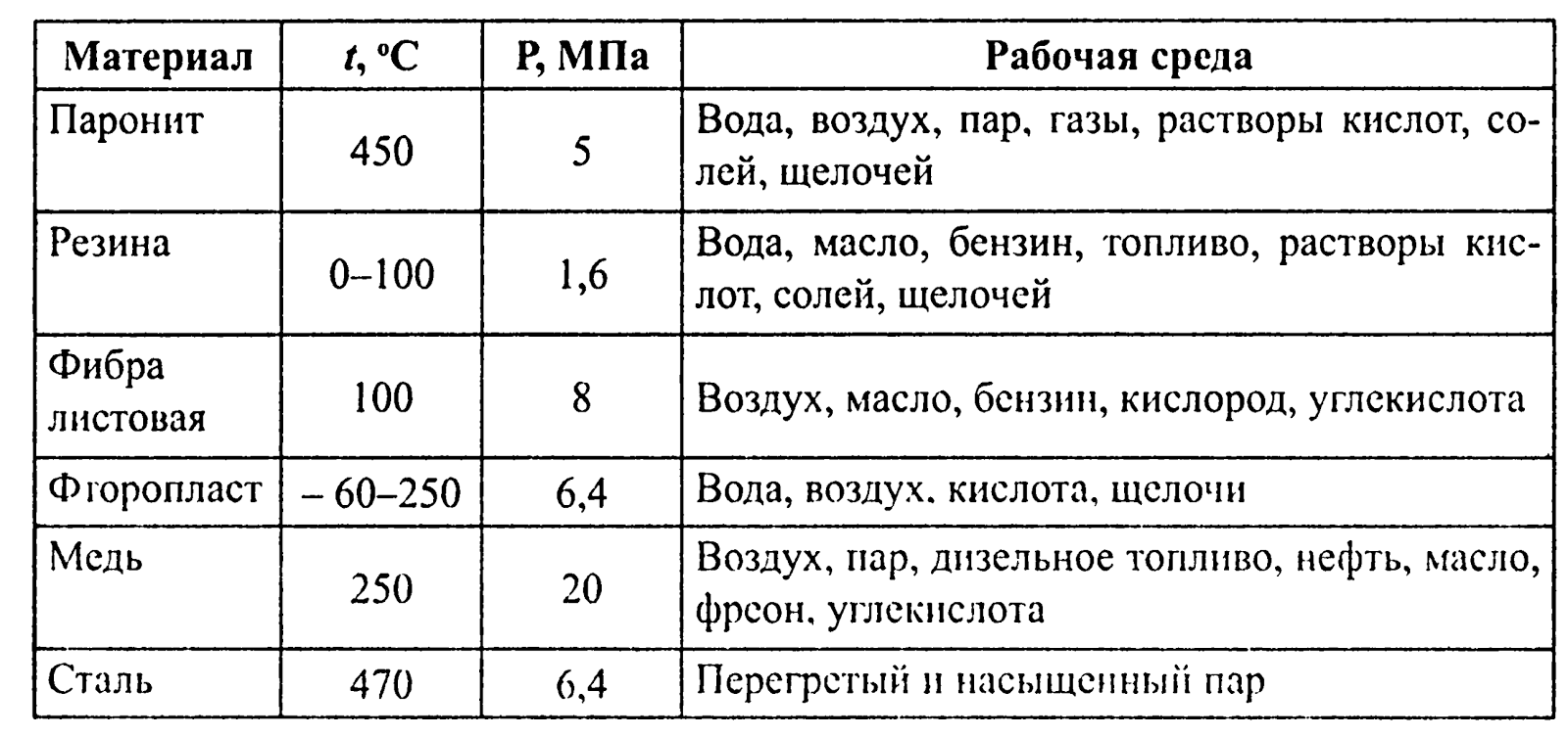
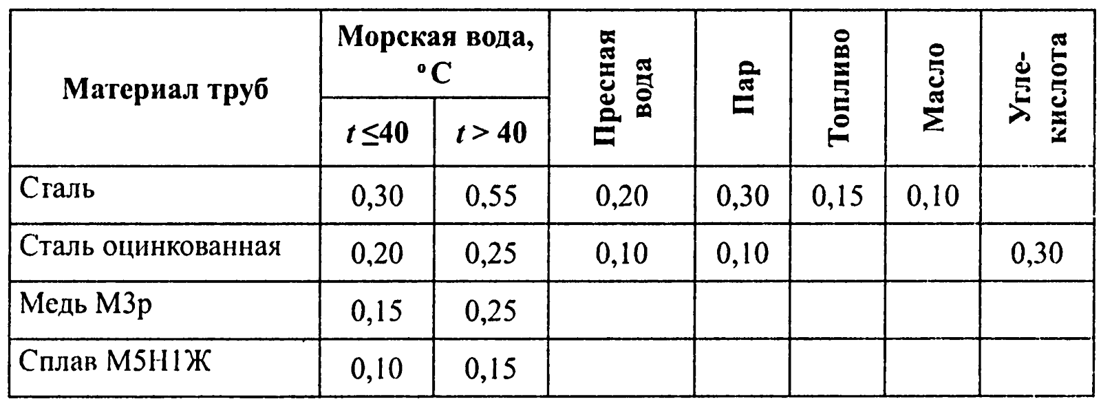
The characteristic defects of valves (valves, plugs, cliquets) of pipelines is the loss of their closure density, which is restored by grinding manually or using mechanical devices. To do this, use fine sandpaper, coarse paste GOI, and then thin paste. At installation of pipelines, various gasket materials are used, which should correspond to the working environment, its temperature and pressure. These materials are shown in the table:
Gasket materials used depending on the working environment, its temperature and pressure:
The density in the flange and choke connections of pipelines is restored by their compression, as it is broken mainly due to the weakening of the tightening of the flange bolts and cap nut.
When the density of the gasket is restored, it is usually replaced.
Under the operating conditions of the vessel, it is possible to eliminate cracks, fistulas and loss of density of pipeline connections. To eliminate cracks and fistulas, welding is used, or defective pipes are replaced with new ones.
If there is no spare pipe on the vessel with the same internal diameter and to preserve the performance of the system, it is necessary to calculate the cross-section area of the main and spare pipes and then find their ratio.
For example, the internal diameter of the main pipe is D1 = 50 mm, and the spare D2 = 25 mm. The area of the bore will be determined by one of the formulas:
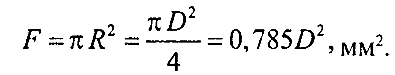
The ratio of the areas of flow areas will be equal to:

This means that in order to maintain system performance, it is necessary to install 4 pipes with a diameter of 25 mm.
In cases where the welding is not possible to apply, apply the methods of temporary elimination of damage to pipes:
- use a soft gasket and a metal lining. Density is ensured by tightening the clamp with a screw;
- method of cell formation (wire winding);
- a defective section of the pipeline is cut out and a new pipeline is installed in its place, or a durit hose, the ends of which are compressed;
- pipe winding fiberglass on epoxy resin, or use other materials.
Separate dents are corrected by heating the pipe to 650-700 C at the location of the defect. Plugs are installed on the flanges, and through the fitting of one of the plugs are connected to the compressed air pipeline and raise the pressure to 0.4 MPa. As it heats up, the dent begins to straighten under the pressure of compressed air in the pipe. To avoid a bulge, a patch is applied to the defective area, and the heated section is cooled with water. The process of manufacturing pipes and compensators consists of blank templates, pipe bending, cutting holes for fittings, welding flanges and hydraulic testing. The templates are made of steel soft wire with a diameter of 6 mm in place, either by replaceable pipes, or by countermaps, or by drawings that were previously redrawn in full size on the plaza. Pipes bend in the hot way with a filler, or cold without a filler, on pipe bending machines. During hot bending of pipes, quartz or pure river sand, dried at a temperature of 150-220 C and sifted through a No. 6 sieve (cell size 3x3 mm), is used as a filler. Rosin is used to fill pipes of small diameter (from non-ferrous metals). Outlets of the pipe are clogged with wooden plugs. When cold bending pipes with a diameter of 25 mm, hand-held machines are used, and with a diameter of 25 to 300 mm - machines with a mechanical drive. The strength of the pipes is checked at hydraulic tests with a test pressure of 1.5–2 times the working pressure (depending on the purpose of the pipeline).
When carrying out repair work to restore the strength and density of the system is subjected to hydraulic testing. Before testing, all pipes are cleaned of dirt, paint and rust, copper and brass pipes are subjected to annealing, followed by cooling in water or air. The annealing temperature of reddish pipes is 550-650 C, brass - 640-680 C, holding time 1 min per 1 mm of pipe thickness.
To increase the life of steel pipelines used metal, paint, polymer and other coatings. Zinc coatings on the pipe are applied by the following methods: thermal diffusion - in a powder mixture; hot - in the melt of zinc; by electroplating.
In the thermal diffusion method, the pipes are filled with a mixture of 80% zinc powder and 20% ground powdered quartz, placed in muffles, covered with a mixture and covered with a lid. The muffles are placed in the oven and incubated for 8-10 hours at a temperature of 480-500 C.
The most widely used method of hot-dip galvanizing, for this pipe is immersed in the zinc melt through a flux pad. In order to increase the resistance of the coating, microadditives of titanium, magnesium and aluminum are introduced into the zinc melt. The holding time of the pipe in the zinc melt bath depends on the required thickness of the zinc coating and the temperature of the melt.
Of interest is the method of increasing the corrosion resistance of ship pipelines made of carbon steel by applying a protective titanium coating on them by diffusion saturation. Diffusion titanation of samples of steel grade 10 and 25 is carried out in a mixture of powder ferrotitanium, fluorspar and sodium fluoride at a temperature of 900-1000 C for 6 hours. As a result of diffusion saturation, a layer of light-gray color up to 1.5 mm thick, strongly bonded to the metal, is formed on the steel. Diffusion titanium coatings on steels are not inferior to titanium alloys in terms of their corrosion resistance in seawater due to the formation of protective films of TiO2 type on the surface of steel. The test results in seawater allow us to recommend titanized carbon steel for operation in corrosive environments containing chlorine ions. At a number of ship repair enterprises, FL-412 phenol enamel, which is a suspension of zinc crown and aluminum powder in bakelite lacquer, is used as a protective coating for pipes. The enamel is applied to the pipelines in three layers, the total thickness of the coating is 250-300 microns. In order to improve the protective properties of enamel painted pipes are subjected to heat treatment at a temperature of 60-80 C for 7-8 hours in fresh water, turbine oil or air. Service life of seawater pipelines reaches 6-9 years.
The following methods are used for fitting and assembling pipes: with intermediate fitting on the vessel; according to the layouts without fit on the vessel; based on sketches and analytical information on mechanized assembly stands.
The intermediate fit method on a ship can be used to assemble downhole pipes with welded flanges, butt-welds, as well as downhole pipes with free flanges on the weld ring.
The fitting of pipes with flanges in place produced in the following sequence. Bent with allowances at the ends of the pipe and the flanges are transported on the vessel and placed in the regular places. Through various movements achieve coaxiality of the ends of the pipes. Scribble scribble line segments allowances. The cutting of allowances and cleaning of the pipe ends on the vessel is done manually, and in the workshop - on stationary cutting and stripping machines.
Pipe assembly with a fit on the vessel has the following features:
- multiple shipments;
- multiple pipe installation on a regular place with the fixation of temporary primitive means;
- trimming allowances and stripping of pipe ends in ship conditions using non-productive means.
The amount of manual labor for this method of pipe assembly is 90%.
To reduce the complexity of the pipe assembly process on a ship, a method was adopted in which the assembly is carried out in the workshop using mockups. The on-site pipe assembly operation is replaced by the operations: making layout parts, assembling at the layout site, and assembling the pipe according to the layout in the workshop. The axial layout is a 10-20 times lightweight pipe model and is a materialized carrier of information on the position of the flanges on the pipe. The layout consists of a rod and false flakes. The core of the model is bent from a steel pipe with a diameter of 25-50 mm on the same template along which the standard pipe bends. The false-flange has a simplified design, compared to the standard flange, it is made of sheet steel with a thickness of 5-15 mm. Manufacturing technology of the layout is not fundamentally different from the technology of manufacturing pipes by the method of fit on the vessel. For the assembly of pipes on models used mock-up stands, including positioners and supporting jacks, placed on a rigid base and having the ability to move along the base in any direction. Positioners are racks, in the upper part of which are placed heads with counter flanges, which can be tilted and rotated, respectively, around the horizontal and vertical axes. Clamps and stoppers are provided for fixing counter flanges.
The way of assembling according to models is improved by improving the designs of the model and the mock-up stand. In addition to the axial layout used frame and articulated layouts. Recently, the problem of assembling pipes is solved by making pipes according to sketches and drawings with coordinates of pipelines and according to analytical information.
The insulated surfaces of ship pipelines are divided into hot and cold.
Insulation of hot piping surfaces is applied to reduce heat loss, prevent burns, and for fire-fighting purposes. The following materials are used as heat-insulating materials: asbestos, asbestos cord, asbestos cloth, felt, crumbled cork, aluminum foil, glass wool, newwel, etc. Cold surfaces with coolant temperature from 10 C and lower are insulated in the same way as hot ones. Before insulation, pipelines are painted in a specific pattern for corrosion protection.
The method of insulation and the total thickness of the insulation layer is determined by the requirements for the piping system.
The test is carried out before the insulation of pipelines.
The compressed air system operating at a pressure of less than 0.5 MPa, as well as pipelines to consumers of periodic action, regardless of the magnitude of the working pressure, is tested with test pressure for the time required to check for air leakage. Leakage is determined by coating the compounds with a soap emulsion.
Testing of the compressed air system with a working pressure of more than 0.5 MPa for leak tightness should be carried out within 2 hours and within 24 hours for cylinders and pipelines with branches to consumers. When the working pressure is reached, the compressors should be turned off, and then after an hour’s interval, it is necessary to measure air pressure in the pipeline and cylinders.
Pipelines for starting compressed air of diesel engines prior to their launch should be subjected to the following density tests:
- the entire pipeline is tested for 10 minutes;
- compressed air cylinders - within 24 minutes (no pressure drop is allowed).
Measurement of air pressure in cylinders should be made not earlier than 5 hours after their filling from compressors, that is, when the air temperature in the cylinders is equal to that of the environment.
The rise of air pressure in the system to the worker should occur gradually, with checking the condition of the pipeline at intermediate pressures. Identified in the test process, defects are eliminated with the pressure removed, after which the tests continue.
The results of tests for tightness of the compressed air system are drawn up by an act of the established sample. Gap - damage resulting from a short-term (accidental) impact in the form of water hammer, defrosting of the pipeline; crack - damage characterized by metal separation; dent - damage in the form of a smooth recess on the pipe surface.
Corrosion and erosion wear include the destruction of metal from both the internal and external surfaces of pipelines, which is of a general and local nature. The general nature of wear is the destruction of pipe metal as a result of corrosion, which spreads over large surface areas with relatively low penetration rates into the metal. The local nature of wear (pitting) is the destruction of metal on relatively small areas of the pipeline surface (“weak” sections). Fistula - local destruction of metal in the form of through holes in the pipeline.
Determination of the technical condition of pipelines is carried out by visual inspection and identification of the nature and extent of existing damage, measurement of external damage and residual wall thickness, conducting hydraulic tests where necessary and comparing the results of the survey with the relevant standards.
The main criterion for determining the technical condition and predicting the residual service life of pipeline elements is the residual thickness of the pipe wall at the time of its flaw detection.
Measurement of the residual thickness of pipelines should be made at least at three points as far as possible from each other and not lying on the same generator (if the wall wear does not exceed 30% of the nominal pipe wall thickness). When this value is exceeded, measurements must be made at least in six points.
The residual thickness of the pipe walls is determined using ultrasonic devices (thickness gauges) such as UT-93P, DM2 or DMZ, and TM-100 or TM-20.
The figure below shows nomograms for determining the allowable wall thickness of pipes made of steel, copper, copper-nickel alloys, depending on their diameter and pressure of the working medium.
Permissible wall thicknesses of pipeline elements corresponding to the limit state:
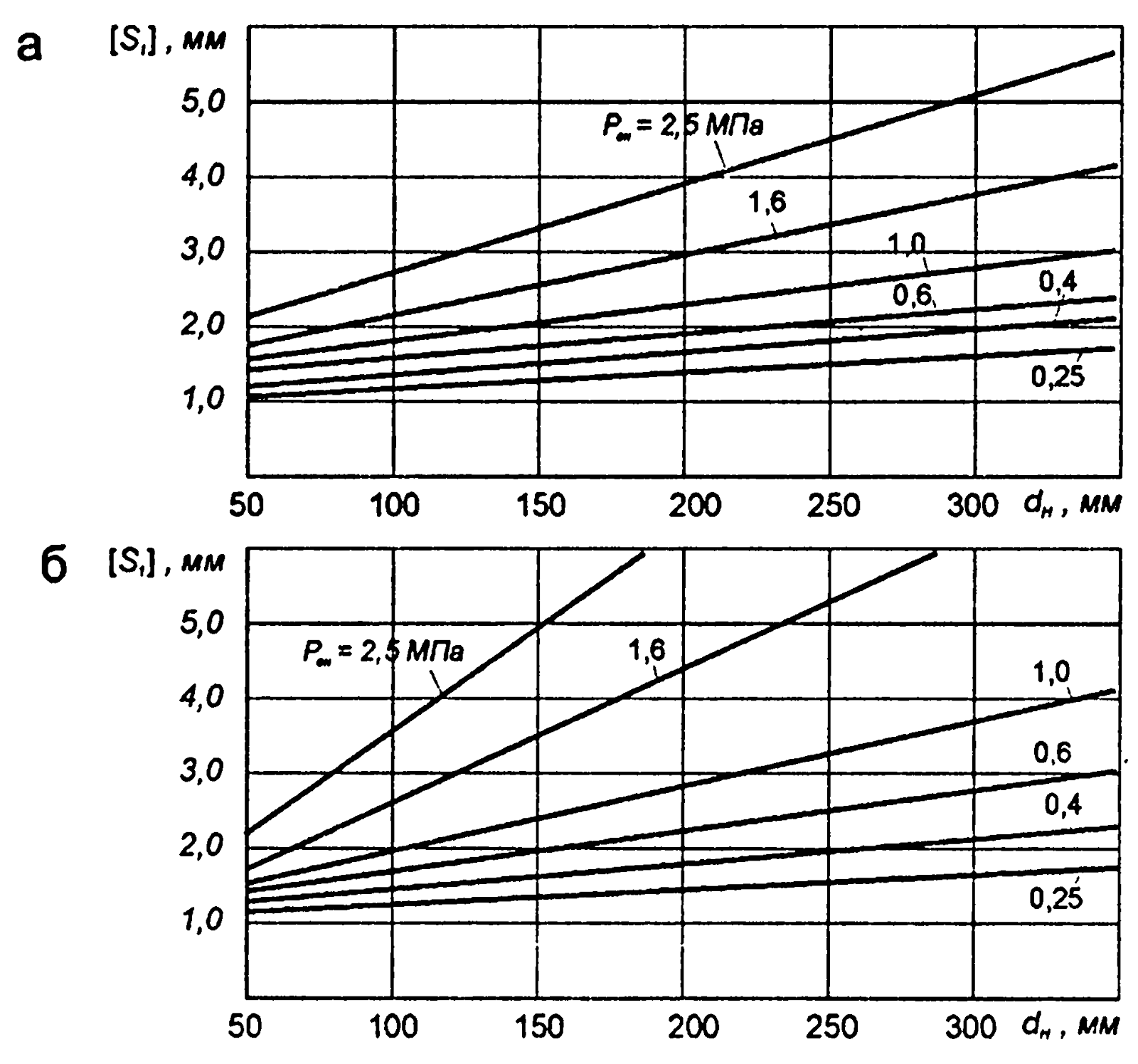
and - from brand 10 steel; b - from copper of brand MZr.
The prediction of the residual service life of a pipeline is based on the linear dependence of its corrosion-erosion wear on the service life from the moment of construction or replacement.
Knowing the residual wall thickness of the pipeline at the time of flaw detection S1, (mm) and allowable (mm), the predicted residual life of the Toast pipeline (years) can be determined by the formula:
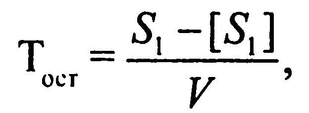
Where V- rate of corrosion erosion wear, mm / year.
The average wear rate for straight pipeline sections is given in the table:
The sewage system provides for the disposal of waste and domestic water.
Wastewater includes:
- drains and other waste from all types of toilets, urinals and toilet bowls;
- drains from medical premises (ambulatories, infirmaries, etc.);
- drains from the premises in which animals are kept;
- industrial waste.
Domestic waters include wastewater from sinks, showers, laundries, bathtubs; drains from galley equipment sinks and other premises of the catering unit.
The service life of ship pipelines of fishing vessels in most cases does not exceed 3-5 years. The seawater piping systems, which account for up to 70% of all failures in ship systems, are particularly prone to corrosive wear.
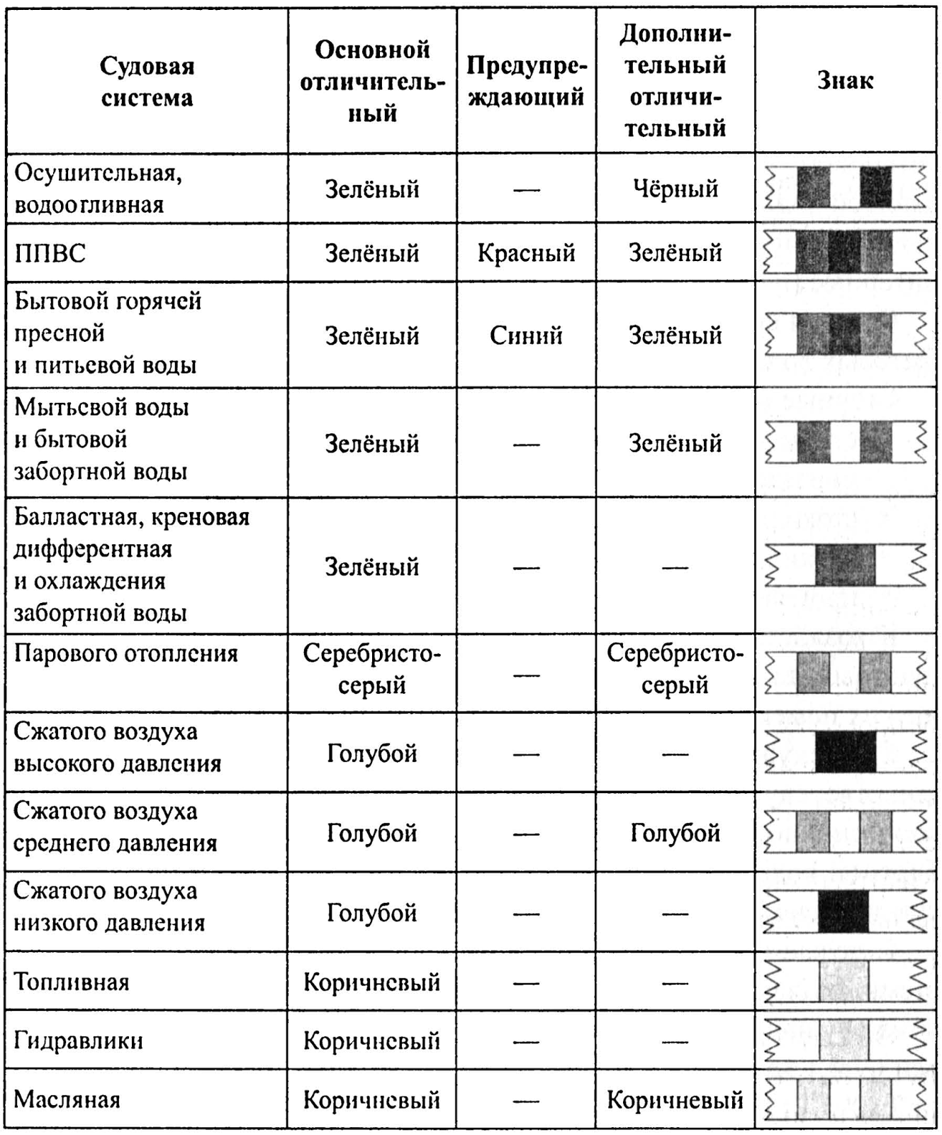
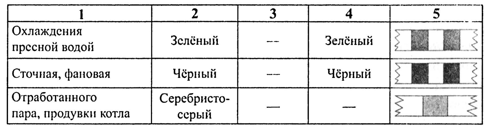
In order to prevent accidents in the repair of pipelines of the system should be different from each other. For this purpose, distinctive and warning signs are put on the pipeline and fittings in the form of rings of a certain color (NBZhR-80, order No. 434 of the USSR Ministry of Fisheries of September 29, 1989, NBZhS, RD 31.60.14-81, of the USSR Ministry of Fleets of 01. 1980. ).
The width of the distinctive rings of 25 or 50 mm, warning - 50 mm. When applying only decals, the distance between the rings should be 25 mm. Rings of warning signs are applied between the rings of decals, without gaps.
Distinctive and warning signs of ship systems:
Ship systems - a set of pipelines, machinery, equipment, instruments, devices and tanks provided on ships of all types and purposes and designed to move liquids and gases. The concept of “ship systems” has been fixed in the technical literature since the late 20s of our century.
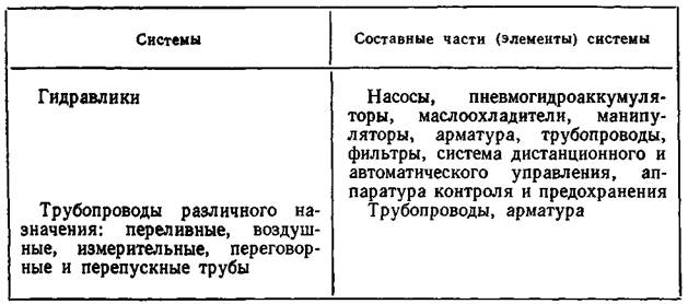
Ship systems are divided into: general shipboard (Table 1.2), designed to achieve proper seaworthiness of the vessel, its survivability and unsinkability (bilge and ballast systems, fire extinguishing, irrigation, flooding, etc.) and serving to maintain the specified habitability conditions (ventilation systems air conditioning, domestic fresh water, etc.); systems used in carrying out cargo and rescue operations (cargo systems for bulk vessels, tank washing, etc.); power plant systems designed to ensure the operation of power equipment (steam generators, turbines, diesel engines, etc.). The ship systems also include pipelines for various purposes: air, measuring, negotiation, overflow and overflow pipes, scuppers of open decks, In ship systems, various environments - water, air, water vapor, fuel, oil, gases (nitrogen, helium, oxygen , carbon dioxide) and refrigerants - are subjected to heat and humidity (heating, cooling, drying, moistening) and energy (compressing, expanding) processing and are supplied to consumers in the tank and removed from them, including overboard. On large modern ships there are 50-60 ship-wide systems and 20-30 power plant systems.
The ship pipeline is an integral part of the ship system and is a combination of pipes, connecting, disconnecting and receiving fittings, fittings, fittings, pipe insulation and protecting them from damage, intended for transporting liquid, gaseous and multiphase media, as well as for transferring pressure . Ship pipelines appeared on the ships of the sailing fleet and served to ensure the flow of water, fresh air and other needs.
Table 1.2. The composition of ship systems and pipelines for various purposes
Continued table. 1.2
Since 1970, in the technical literature, the term “ship pipeline” has designated ship power systems (for example, main steam pipeline, fuel pipeline).
The ship pipeline has a trunk through which the floating medium is diluted or in which it is collected, and branches along which the floating medium is brought to the group or single consumers or diverted from them. The trunk line is linear, dual-line, and circular.
Pipelines are made of separate pipes interconnected by detachable and one-piece methods. Pipes steel, brass, duralumin, plastic, rubber, from copper-based alloys round and rectangular (in ventilation and air conditioning systems). Flanged, socket, durite and choke-type detachable joints, welded and soldered one-piece joints.
For passage through decks and bulkheads use deck and bulkhead cups, privarshi and vvarshi. In order to compensate for temperature expansion and bending of the hull of the vessel, compensators are installed (lyre-shaped, bellows, etc.). Thermal diffusion hot and galvanic galvanizing of steel pipes, oxidation of aluminum pipes, silicate-enamel and film-forming (plastic) coatings are used to protect pipelines from corrosion, and they include the installation of protectors. Pipelines with a cold environment in residential and office buildings are insulated with felt, expanding agent, with a hot environment - with Newvel and sovelite shells, asbestos cloth and pukshnur. The color of the pipeline depends on the purpose of the ship system. Thus, the pipelines of the fire extinguishing system are painted red, the ballast system is green, the waste pipe is the same color as the room with black rings.
Bilge systems are a combination of pipelines, machinery, devices, instruments and devices designed to periodically remove overboard water that accumulates in the vessel’s bilge and during operation due to leaks in the hull and pipe sheathing joints, as a result of washing the interior ( drainage system), and also for removal overboard from the ship’s premises a large mass of water received in the event of an accident, hull damage or fire extinguishing (drainage system).
The accumulated water is concentrated in bilge and prefabricated wells arranged in the double bottom space in such a way that the receivers of the drainage system located in them ensured the removal of water during a ship's heel by 15 ° and a trim of 5 °. The receivers are protected by nets, in the engine rooms at the water intake they install mud boxes in which dirt is deposited. Ballast pumps and other systems can be used. To protect the sea from pollution, oily bilge water is cleaned from oil products (separation, sludge) before discharge overboard. Portable and stationary submersible pumps with a capacity of 1000-2000 m 3 / h are used in drainage systems. Due to the rare inclusion in the action drainage systems are often combined with ballast. When used for dewatering and drainage of stationary and portable water-jet ejectors, the working water is supplied to them from the water extinguishing system. Vessels of all types and purposes will be equipped with bilge systems in one form or another.
Ballast systems - a set of pipelines, machinery, devices, instruments, devices and tanks designed to receive ballast water in tanks, transfer and remove it from the ship in order to change the draft and stability of the ship (ballast system) and level or create artificial roll (roll system) and trim (trim system) when performing loading and unloading operations, swimming in ice and in emergency situations, as well as in connection with the expenditure of fuel and water.
Ballast systems appeared on ships in the middle of the 19th century, when, when changing solid ballast (sand, crushed stone, stones), they began to be replaced with liquid, outboard water. At first 20 in. ballast systems were also used to receive and remove fresh water stored in double bottom tanks.
On large vessels, oil platforms, icebreakers for the rapid transfer of large masses of water in ballast systems used axial pumps, including reversing action, and the pipelines are in the form of hull corridors with discharge channels communicated with the atmosphere. The functions of the bank and trim systems on a number of vessels are carried out by a single ballast system, which in small vessels can be combined with bilge systems.
Water extinguishing system - a set of pipelines, machinery, devices, devices and devices, including receiving kings, stationary fire rods and fire hoses with portable barrels, designed to receive from the side and supply water to the fire centers in the form of compact or sprayed jets into various the ship’s premises and open decks, as well as other vessels.
Water extinguishing systems began to be installed on the ships of the sailing fleet in the 18th century. (with manual water pumps), and to date they continue to remain the main means of fighting fires. The technical literature also includes the terms “water-extinguishing system” and “water fire-fighting system”. From the fire extinguishing system, water is also supplied to the spraying systems, water curtains, irrigation and sprinkler systems. Provides for the selection of water for ejector drainage systems and drainage systems and flooding systems, as well as for various ship needs (flushing fecal tanks, anchor chains and gates, washing decks and blowing kingston boxes).
Pressure line on small vessels of the linear type, on the remaining vessels of the ring type with several bridges, separated by shut-off valves; centrifugal pressure pumps with electrically or steam driven disperse in different compartments. Apply pumps driven by an internal combustion engine. Sanitary, ballast, sewage and other seawater pumps can also be used as fire pumps, if oil residues are prevented from entering the water. Pressure in the pressure line up to 1 MPa; water flow through the portable barrel to 7 l / s. On passenger ships carrying more than 36 passengers and ships with enhanced fire protection to ensure that fire extinguishing systems are always ready for pressure, the line pressure is supported by the operation of one of the pumps or by means of a pneumatic tank included in the water extinguishing system or in the system of domestic outboard water. Water extinguishing systems are provided for each self-propelled and non-self-propelled vessel having a power plant with a capacity of more than 74 kW (100 hp.) And a crew of three or more.
Water spray system - a set of pipelines, instruments and devices intended for supplying water from the side and spraying to extinguish a fire in the engine rooms and boiler rooms, as well as in other ship's premises where liquid fuel is used. The term “drencher system” is also found in literature. The slit-type sprayers installed in the system or drenchers, unlike sprinklers, do not have a valve and their outlet openings are constantly open. The water supply is carried out from the water extinguishing system. Start-up is done manually by valves installed in the engine room, boiler rooms and other rooms; remote drives are provided for launching the system from open decks. Water consumption up to 0.3 l / s per 1 m 2 of irrigated area. The water spray system is installed on ships of various classes and purposes.
Irrigation system - a set of pipelines, machinery, devices, devices and devices designed to supply water to irrigation nozzles to extinguish a fire or to lower the temperature in storage facilities for flammable substances, in dry loads, as well as for irrigation in case of fire decks, bulkheads , watches, descents, aisles, etc. Water is supplied to the irrigation system by water extinguishing systems. In contrast to the systems of sprinkler and water-spraying, water is supplied to the premises by more dense jets.
Since the 1950s, irrigation systems for the storage of explosive and flammable substances have been carried out mainly with automatic start-up.
from temperature sensors installed in protected premises and acting on high-speed water supply valves. Automatic start is duplicated by remote drive from the open deck. The pipelines of the irrigation systems of these premises can be constantly filled with fresh water, and the pressure in them is maintained by means of a pneumatic tank, the volume of which ensures the supply of water for the time required for the subsequent supply of seawater from the fire extinguishing water system. The irrigation intensity of the storage bulkheads is 0.2 l / s per 1 m of the perimeter of the irrigated surface, and the racks 0.4 l / s per 1 m 2. Water consumption for irrigation of gatherings, passages of 0.083 l / s per 1 m 2, mines output 0.5 l / s per 1 m of the perimeter of the irrigated surface. Irrigation systems provide for ships of various classes and purposes.
Sprinkler system - a set of pipelines, machinery, devices, instruments and devices designed to automatically feed and dispense water in cabins, cabins, saloons and offices of ships at a temperature higher than the set in them, which ensures the prevention or suppression of a fire. With the Grinnell heads, sprinkler systems began to be used on ships before the Second World War. Automatically triggered spray nozzles - sprinklers are placed on the ceilings of protected areas to evenly cover the entire area of the decks with fine sprayed water. The deck area irrigated with one sprinkler is up to 9 m 2. The pipelines of the system are constantly filled with fresh water; The pressure in them is maintained by means of a pneumatic tank, the volume of which ensures the supply of water for the time required for subsequent supply of overboard water from the pump of the sprinkler system or from the water extinguishing system. Water flow through the opened sprinkler 1.5 l / s, the pressure at the outlet of 0.15 MPa. The opening temperature of the sprinklers on vessels sailing in temperate zones, 68 ° C, in the holds 79 ° C, in drying rooms and galley 141 ° C. Sprinkler systems are installed on passenger ships carrying more than 36 passengers.
The water curtain system is a set of pipelines, mechanisms, instruments and devices designed to create solid water curtains that prevent the spread of fire, steam and gases that protect people from thermal radiation, cooling the hull structures of the vessel. These systems are combined with a water extinguishing system. Water is supplied to the slit water sprayers. Water consumption for the creation of 1 m water curtain 1.17 l / s. Start is made manually. Water curtains provide for rescue vessels, fire boats, ferries, etc.
Flooding system - a set of pipelines, equipment, instruments and devices designed to fill the storages of explosive and flammable substances with water in the event of a fire or explosion hazard. Flooding systems first appeared on the ships of the sailing fleet and served to flood the kryuit cameras. Depending on the location of the storage facilities, gravity or forced flooding systems are used. Storages located below the waterline are flooded by gravity under the pressure of seawater. The storages located above the waterline are forcibly flooded with the help of water jet ejectors, to which water is supplied from the water fire extinguishing system, which ensures the suction of large masses of seawater. For the release of air in the process of flooding the storehouse is equipped with air tubes.
Steam extinguishing system - a set of pipelines, appliances and devices designed to supply water vapor to fuel tanks to extinguish burning fuel. In the technical literature, the term "steam suppression system" is also found. The system uses saturated steam taken from steam generators and reduced to a pressure of 0.5-1 MPa. Steam extinguishing systems provide steam for filling half of the volume of protected premises within 15 minutes. The intensity of the steam 1.33 kg per 1 m3 volume of the room. Systems are used on ships with steam generators (main, auxiliary, utilization boilers, etc.).
The inert gas system is a combination of pipelines, machinery, instruments, devices and tanks designed for cooling, cleaning from soot and sulfur oxides, drying and supplying flue gases to cargo spaces of oil tankers, oil operators and gas carriers to create an explosion-proof and fireproof atmosphere with low (up to 5-6%) oxygen content. Before World War II, it was known as the Harker System. In the USSR, the first inert gas system was installed in 1952 on the Volodarsky river steamer. This system was widely adopted in the 60s with the advent of large tankers and gas carriers.
Gases are taken from the chimneys of the main and auxiliary boilers (less often from diesel chimneys) or produced in autonomous generators. Cleaning and cooling of gases are performed with outboard water in contact devices (scrubbers with irrigated nozzles, cyclone-foam, etc.). To improve the purification of gases from sulfur oxides alkaline solutions can be added to the seawater. On gas carriers, after cleaning and cooling, flue gases are dried using refrigerating machines and adsorbents, which excludes freezing of moisture in the cargo area. In accordance with the rules of the International Maritime Organization (ICMO), all oil tankers and vessels for the transportation of oil products with a deadweight of over 20 thousand tons will be equipped with systems inert gases. Calculations of these systems largely depend on their type.
Drinking water system - a set of pipelines, machinery, devices, devices, devices and containers designed for receiving, storing, disinfecting, salinizing and supplying drinking water to the galley, drinking lagoon, saturator, canteens and other places of consumption, as well as for drinking water to other vessels.
The simplest drinking water systems were used on the ships of the sailing fleet. Work on the creation of drinking water systems on the ships of the Russian fleet began in the mid-19th century. They underwent intensive improvement in the 50s of our century.
Fresh water from the shore, from another vessel or from a desalination plant enters the reserve tank, from where it is pumped into the pneumatic tank, passing decontamination and mineralization if necessary, and then under pressure to consumers. Spare tanks often perform insertion in the hull; their surface is protected with cement mortar, synthetic materials and paints. A vertical cylindrical pneumatic tank is partially filled with water and compressed air, has a pressure switch acting on the pump start-up when the water level in it decreases. Decontamination is carried out by chlorination, ultraviolet radiation using bactericidal lamps by treatment with silver in ionators, ozonation of water, and mineralization by the addition of solutions of salts and alkalis. Drinking water systems on some vessels are combined with wash water systems into a common household freshwater system. On sea vessels of the unlimited navigation area, drinking water consumption per person per day is 40 liters and more (on passenger ships 80-90 liters).
The wash water system is a set of pipelines, machinery, devices, appliances, devices and containers designed for receiving, storing, disinfecting, heating and supplying to showers, baths, baths, laundries, washbasins and other places of consumption of cold and hot fresh wash water and for transfer it to other vessels. These systems began to be applied on ships at the end of the 19th century.
Stocks of washing water are stored in side or bottom tanks, in forps, aft peaks and other compartments of the vessel. The wash water system is different from the drinking water system by the presence of a water heater, tank, pump and hot water pipeline. Water is heated to 60-70 ° C with steam. The preset heating temperature is maintained automatically by a sensor located in the hot water tank and acting on the steam valve. Wash basins supply washing water, purified and disinfected similar to drinking water. On some ships, wash water systems are combined with drinking water systems into a common household freshwater system. On sea vessels of the unlimited navigation area the consumption of wash water per person per day is 60 liters and more (120-150 liters on passenger ships).
Household fresh water system - a set of pipelines, machinery, devices, devices, devices intended for receiving, storing, sanitary-hygienic processing and supplying to the places of consumption of fresh water necessary for drinking, cooking, washing, washing and other domestic needs. These systems are used on ships where separate systems for drinking and washing water are not provided. The systems also provide the transfer of fresh water to other vessels. Domestic freshwater systems appeared in the 60s mainly on fishing vessels of small and medium displacement. In the case of their use, the possibility of drinking water for drinking is excluded, the length of pipelines is reduced, the number of valves and tanks decreases. Consumption of fresh water on passenger ships 200-240 liters per day per person.
Domestic seawater system - a set of pipelines, machinery, equipment, instruments and devices intended for feeds ”
outboard water to sanitary-household equipment: to flush uniforms and urinals, to potato washers, to cool water heaters and immersion heaters, and to other consumers. The water received from the board is pumped into the tanker, from where it is sent to the places of consumption. Spare tanks are absent. On some ships, jumpers are provided between the system of domestic seawater and the wash water system for washing with seawater when sailing in the open sea, as well as the water extinguishing system - to maintain constant water pressure in the latter.
Sewage systems - a set of pipelines, machinery, devices, instruments, devices and tanks designed for collecting, processing (cleaning and disinfecting) and removing from the vessel fecal and waste water from latrines, medical premises and premises for transporting animals, as well as for collecting and removal from the vessel of domestic water from washing, baths, laundries, galley and other outbuildings.
The simplest sewage systems first appeared on the ships of the sailing fleet. In the technical literature, the term "waste-drainage system" is also used. Work on the improvement of sewage systems began in the 70s due to the tightening of requirements for the protection of the marine environment from pollution.
Fecal, waste and domestic water when sailing in the open sea are removed overboard by gravity through pipelines laid with a slope towards the side. At the side openings located above the waterline, storm shutters are installed to prevent the backward movement of sewage when the discharge openings are submerged in water in rolling conditions. When the vessel is in coastal waters and is moored in the port, fecal and domestic waters are discharged and disinfected by chemical, electrochemical or biological methods before discharge overboard. In the absence of devices for cleaning and disinfection they are collected in tanks, and then pumped into floating or shore tanks or discharged into the open sea.
Scayers of open decks - a set of pipelines with receivers designed to divert overboard water entering open decks during rough seas as a result of precipitation, fire extinguishing, cleaning, etc. Receptacles are installed in places of possible accumulation of water. From scuppers, water is drained by gravity through the scaffold pipes to the underlying open decks or directly overboard. The scuppers of open decks provide for ships with multiple decks and superstructures.
The ventilation system is a combination of pipelines, mechanisms, instruments and devices designed to receive and supply fresh air to the ship’s premises and to remove polluted air from them in order to ensure air exchange and air mobility.
The first ventilation systems in the form of "windsales" through which air entered the premises were used on sailing warships. Invented in 1741, the ship "fan" with blacksmiths and a wooden centrifugal fan with a manual drive were described by P. Ya. Gamaleem in 1804. Great attention was paid to ventilation systems in the Russian fleet from the second half of the 19th century.
Air exchange is carried out in a natural way with the help of rotary deflectors and ejection heads installed on open decks and superstructures, and forced (artificially) centrifugal and axial fans.
Reception of outside air and removal of polluted air during forced ventilation is carried out through deck mushroom heads or shafts with louvers and placed in superstructures or chimney covers.
Latrines, sinks, showers, bathrooms, laundries, battery rooms and other rooms where vapors and gases are emitted are equipped with exhaust ventilation systems with air leaking from the rooms, and cabins, cockpits and service rooms (in the absence of comfort air conditioning systems) with air-supply systems with exit of polluted air through door grilles into the corridor. Mixed supply and exhaust systems equip engine rooms and boiler rooms, aggregate and cargo rooms (in the absence of a technical air conditioning system). To reduce noise, fans are placed in enclosures, sound-absorbing inserts are installed in pipelines. Ventilation systems are used on ships of all classes and purposes.
The comfort air conditioning system is a combination of pipelines, mechanisms, devices, instruments and devices designed to receive, heat, cool, humidify the air and feed it to cabins, cabin companies, saloons, cockpits, medical and service spaces of the vessel, which ensures maintenance they are favorable for the well-being of people of air parameters: temperature (when swimming in the tropics 25-28 ° C) humidity (40-60%), mobility (up to 0.5 m / s) and gas composition - regardless of external conditions.
These systems first appeared on ships at the end of the 19th century. By 1930, there were about 100 ships in the world equipped with systems of comfortable air conditioning. Their rapid development began in the late 50s.
Mechanisms (fans) and devices (heaters and coolers, air humidifiers) are arranged in a central air conditioner. Water vapor is supplied to the heaters under pressure of 0.3-0.5 MPa or hot water, to the coolers - cold water or refrigerant (freon) from the refrigerating machine. From the central air conditioner to the air distributors installed in the rooms, the air enters through one or two channels. Speed in channels 18-20 m / s. In single-channel systems, heat exchangers can be installed in the air distributors for additional air preheating (steam, water or electric). In two-channel systems, air enters the air distributors with different temperatures, which allows you to mix it in the right proportion. Reception of outside air and removal of polluted air are performed in the same way as in the ventilation system. At present, ships of all classes and purposes are equipped with comfort air conditioning systems.
The technical air conditioning system is a combination of pipelines, mechanisms, devices, instruments and devices intended for receiving, heating, cooling, dehumidifying the air and supplying it to cargo and other premises of the vessel, which ensures that they maintain regardless of the external conditions of the air parameters environments required for the preservation of cargo or equipment, instruments, etc., as well as to reduce corrosion of metal hull structures.
The first samples of shipboard dryers for technical air conditioning appeared in the late 30s of our century. Widespread technical air conditioning system received in the late 50s.
Air drying is carried out by solid water absorbers (adsorbents), liquid (absorbents), and also when cooled with the help of a refrigerating machine. Silica gel and zeolite are used as adsorbents, absorbents - salt solutions - chloride, less often lithium bromide; Fibrous materials impregnated with salt solutions are used.
Dry and cooled air is supplied by fans to the cargo space, to the instruments and other equipment. To remove water from the absorbers (desorption), additional fans are installed. Reception of outside air and its removal from the premises are made similarly provided for in ventilation systems.
Steam heating systems are a combination of pipelines, apparatuses, devices, and devices designed to supply water vapor to heating devices — steam heaters and remove spent steam and condensate from them, which provides heating for the ship’s premises.
Before the Second World War, these systems were the main means of heating the residential and office premises of ships. With the advent of comfort air-conditioning systems in the 50s, they were used mainly for heating machine and boiler rooms (when the vessel was stationed), mechanical workshops, utility rooms, sanitary facilities and sanitary facilities, corridors and vestibules.
Single-conductor systems are used in which fresh, spent steam and condensate move along one pipeline. Behind the heaters are placed float coders, thermostatic with bellows or membranes and thermodynamic. The steel or copper heaters in the form of finned tubes are installed with easily removable covers, the temperature on the surface of which does not exceed 70 ° C. Fresh steam pressure up to 0.3 MPa, temperature 130-135 ° C. Steam heating systems are used on most self-propelled vessels with steam generators.
Systems of rescue ships - a set of pipelines, machinery, devices, devices "devices and tanks designed to perform certain functions on rescue ships: scouring of soil with water jets around a sunken ship or sitting on the ground, sucking the soil (sand and sludge) from the sunken premises vessel, pumping out water from the flooded premises of an emergency vessel, receiving, storing and supplying compressed gases (nitrogen, helium and oxygen), preparing and supplying gas mixtures for diving operations and charging cylinders for breathing apparatus. Rescue ships are also equipped with fire extinguishing systems, water curtains and other fire fighting equipment.
Systems of bulk vessels - a set of pipelines, machinery, devices, instruments, devices and tanks designed to receive, transfer within the vessel and unload liquid cargo (cargo system), pump out the cargo system of unselected cargo liquid system (stripping system) from cargo tanks tanks of safe pressure and gas exchange in the process of receiving, delivering and transporting liquid cargo (gas exhaust system), supplying detergent composition to washing machines (hydro monitors) and subsequent removal of washing products from cargo tanks (tank washing system), irrigation of the external surfaces of cargo tanks with seawater in order to reduce the temperature of the cargo and reduce its losses from evaporation (the irrigation system of cargo tanks). The literature also uses the term “special systems of oil tankers”.
Cargo centrifugal and stripping piston pumps are located in the pump room. Highways are laid in the bottom corridor and along the cargo deck. Sink tanks produce crude oil and heated seawater with detergent composition. Bulk vessel systems are used on tankers and oil tankers carrying oil.
Air pipes - a set of pipelines and devices designed for communication with the atmosphere of tanks filled with liquid, cofferdams and other compartments of the vessel. The upper ends of the pipes, which are led to the open decks, are bent 180 °, as a result of which they form a “goose”, or they are provided with protective caps or stop floats to prevent water from entering them during a wave raid. Air tubes of fuel and oil tanks have fire barrier nets - flame interrupters, air pipes of tanks with drinking and wash water-dust filters. The diameter of the pipes is 50 mm and higher; they can be combined with the measuring pipes.
Measuring tubes - a set of pipelines and devices designed to measure the level of liquid in tanks, tanks, bilge, cofferdams and other storages. Measuring tubes with rails with divisions (feet) are placed in them are the simplest devices used even on the ships of the sailing fleet. Measuring pipes are displayed on decks or double bottom flooring in places convenient for measuring. From above, they are closed with a lid. The fluid level is determined by the wetted surface of the slats. Measuring tubes can be combined with air tubes.
Negotiation pipes - a set of pipelines and devices intended for internal voice communication, carried out by personnel between the premises or posts of the vessel. They are the simplest means for transmitting commands and information. The terminal processes of the speaking tubes provide a mouthpiece and a whistle for a ring signal. Along with the use of radio communication equipment, many modern ships also equip with negotiation pipes.
End of work -
This topic belongs to:
GENERAL SYSTEMS, THEIR OPERATION AND MANAGEMENT
On the site read: "GENERAL SYSTEMS, THEIR OPERATION AND MANAGEMENT"
If you need additional material on this topic, or you did not find what you were looking for, we recommend using the search in our database:
What we will do with the resulting material:
If this material turned out to be useful for you, you can save it to your page on social networks: