Worm gear reducer. Worm gear
Various devices and mechanisms for transforming torque and changing its direction have been used since ancient times, but only modern gearboxes are able to cope with the loads that a person needs to transform in the 21st century. Worm gear is one of these "devices" used to change the gear ratio of the shaft rotation.
This device has advantages and disadvantages, but compared to the wooden gears used in ancient Egypt to irrigate the fields, the worm gear is a perfect device, in all respects.
Advantages of worm gearboxes
Among the advantages of this mechanism for torque transformation are the following advantages:
High gear ratio
Worm gear allows you to transmit torque with a ratio of up to 1000/1, which is almost impossible to implement with other technical solutions.
Compactness
Worm single-stage gearbox has small dimensions, so this mechanism and the engine can be combined in one case.
Noiselessness
Compared to other gearboxes, the worm gear produces less noise during operation.
Smooth ride
Transmission of torque through a worm gearbox, allows you to achieve perfect smoothness of the mechanisms connected to this device.
No backstop
If the gear ratio of the worm gearbox exceeds the value of 35/1, the effect of “reverse stroke” is completely absent. In this case, the drive wheel cannot be turned with a small angle of the worm's rise. If this indicator is too small, the reverse lock will occur with a smaller gear ratio.
The disadvantages of worm gearboxes
This mechanism has drawbacks that impose significant restrictions on the use of a worm gear, if the power of the unit exceeds 60 kW. The disadvantages of this type of gearbox include:
Low efficiency
In comparison with other devices for torque transformation, the efficiency of a worm gearbox is much lower, therefore, where high smoothness and low noise are not required, these mechanisms are not applied for economic reasons.
Heat
In spite of the fact that the worm gear is in working lubricant during the whole service life, significant heating still occurs as a result of friction between the metal worm and the driven gear.
This undesirable effect is especially strong if the power of the unit exceeds 16 kW.
It is impossible to apply this design if the power of the transmitted torque is too high
Design features, as well as low efficiency, do not allow using this device for high-power installations. The most common mechanisms in which the implemented method of worm gear torque does not exceed 15 kW.
Big gap between the shafts
This problem manifests itself with significant wear of the worm drive and is of greater importance than in other types of transmission mechanisms.
Types of worm gearboxes
Worm gearboxes can vary significantly depending on the scope of the mechanism.
The main differences that can be used in the design:
- Different number of visits;
- Material details;
- Thread direction;
- Thread profile;
- Types of screws used.
These differences may be present in various combinations. What types of worm gearboxes the engineer decides to use at the design and development stage of devices and mechanisms using these types of torque transmission.

Design worm gear
Making a worm gear with your own hands is almost impossible. The calculation of the worm gear should be carried out by a qualified technician. When the drawing is done, all parts for it are made only from materials of good quality, otherwise the gear mechanism may fail after a short work. The worm gearbox assembly should also be carried out by an experienced master. Failure to comply with this rule can significantly reduce the operational life of the part, because besides the correct installation of the shafts, careful adjustment of the worm gear will be needed.
If it is necessary to use a worm gearbox in order to install an improvised torque transmission mechanism, then in this case it is better to use ready-made used products from equipment that use this type of torque transmission. In the case when an independent development of new devices is being carried out, which will be patented, the design of a worm gearbox should be ordered from the design bureau engaged in similar developments.

Principle of operation
The basis of the entire transmission mechanism is a worm-shaped lead screw, in honor of which these types of gearboxes got their name. The worm screw interacts with the gear, the axial shaft of which is located at a right angle. As a result of this coupling, a transformation of the high rotational speed of the input shaft with a low torque occurs, and the rotation of the output shaft with a small frequency, but significantly greater force. The layout of the worm gearbox may be different. If the worm gear shaft rotates at a speed below 5 m / s, then the worm is located below, if the speed is higher, then the gear with the upper worm is installed.
Most of the mechanisms of this type are used with a single gear stage, but sometimes a two-stage worm gear can be used to adjust the ratio.
If the shaft rotation speed is more than 10 m / s, bearings and hypoid gears must be lubricated under pressure. If the motor is low-speed, then natural circulation of oil during rotation of the transmission is sufficient.
Worm gear oil should be of high viscosity, otherwise the wear process of the most loaded parts of the gearbox will be significantly accelerated.
Repair gear
Simple repair worm gear can be done on its own. If the motor and drive are combined in one case, then the mechanism should be carefully disassembled.
The part of the common crankcase in which the drive is located is also subject to parsing. If the design of the worm drive is made for a high-speed motor, then before proceeding to the analysis of the gearbox, it is necessary to drain the transmission oil from the housing.
High-quality bearings are used in this type of gearbox, so the need for repairs most often occurs if the gear and the worm are worn out over the limit values. The working pair is always subject to simultaneous replacement with a complete repair kit, which, before entering the distribution network, must be properly selected and tested on a special stand.
If the wear of the worm pair is insignificant, then the gap can be eliminated using special washers-gaskets on the driven shaft.
The design of the worm gearbox also allows adjustment of the gearing of the gear with the worm without disassembling the body. For this purpose, a bolt is used, which is built into the housing. If there is a drawing of the device, then you can easily determine where the gear is regulated. If there is no drawing, then an indirect sign of the adjusting bolt will be the presence of a lock nut on it, which is used to fix the adjusted clearance between the worm and the gear wheel. It is extremely rare for gearbox bearings to require replacement. Typically, the drive is equipped with high-quality ball bearings, which do not require replacement or repair during the entire operational life of the part. Bearings can only be damaged if the drive has been used for a long time without lubrication or with the use of low-quality lubricants.
Professional mechanics, as well as engineers involved in the design of this type of gearboxes, do not recommend using a worm drive if the transmitted power exceeds 200 kW. The design of the worm gear does not allow to cope with such loads, due to excessive heating during operation. If the power of the device is in the range from 60 to 200 kW, then in this case it is also necessary to develop a drawing in which the forced cooling of the oil will be indicated, and the correct selection of materials from which the worm and gear of the transmission mechanism will be made.
The kinematic system of the device must be depicted in such a way that the rotation of the driven gear is located at right angles to the rotation of the input shaft of the worm. It is also necessary to make an accurate description of every detail that is used in the transmission mechanism. Bearings should also be indicated on the diagram, and the drawing should indicate the diameter of the seat for them.
The operation of the worm gearbox is possible in any weather and climatic conditions, but when operating the device in the northern regions of the country, it is necessary to use special oils and lubricants that do not freeze at low temperatures.
The worm gearbox is a small-sized low-speed mechanism, so if you need to save working space with a significant ratio of the gear ratio, then this unit will be beyond any competition among other models of gearboxes.
The range of application is extremely wide. Conveyors, conveyors, elevators, pumps, mixers, gate drives, metalworking machines, including for milling operations. Where a budget solution is needed to reduce the drive speed and increase the torque in the absence of significant shock loads and low frequency of inclusions, put a worm gear there. However, this is still a very categorical statement. Without pretending to absolute infallibility against the truth, I will try to formulate basic recommendations for the use of worm gearboxes:
1. If self-braking is not required, and the gear ratio of the gearbox must be greater than 25 - use cylinder-worm gearboxes. The efficiency of such a gearbox will be higher due to a decrease in the gear ratio at the worm gear. Accordingly, there will be a saving in energy costs and an increase in the service life.
2 Do not put the worm gearboxes in the drive mechanisms under shock loads. During long-term work with blows, the worm gearbox may overheat, and its resource will sharply decrease. The author of these lines witnessed boiling up of oil in a gearbox transmitting power of 4 kW after several hours of its work as a drum drive for a scouring device, which was affected by a periodic shock load from a knife, cutting off worn-out tire treads.
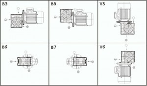
3. Of great importance is the scheme of installation of the gearbox in space. The basic and most recommended under the terms of transmission lubrication is the scheme when the axis of the worm is at the bottom and the axis of the wheel is at the top:
A different orientation in space is possible; when ordering, carefully consider the conformity of the designation of the location of the gearbox with reality! If there is a discrepancy, the oil can flow out of the gearbox, the worm can run dry or, on the contrary, be completely immersed in oil. All this leads to a sharp reduction in the resource. With the top location of the worm, technical literature recommends reducing the value of the nominal torque at the output by 20%.
four . The use of a jet rod or flange mounting is more preferable than installing a gear on the legs. See p. 6 “Benefits”.
5. I do not recommend the use of worm gearboxes in positioning systems. The play in the play can negatively affect the accuracy (here, of course, everything depends on the specific conditions - if the output shaft is connected, for example, with a lead screw having a small pitch, and the required positioning accuracy of the nut is ± 1 mm, the worm gear is quite suitable).
6. When choosing the type of gearbox as applied to the worm gear, it is always necessary to be aware of the possibility of the appearance of inhibition and everything that follows from this property. Do not put the worm gear on the wheelset drive of the cart, if it is sometimes necessary to roll it manually. It will be hard to roll.
7 Before launching the new gearbox into work under load, it is recommended to run it in idle mode (without working load or with reduced load) for 15 ... 20 hours to work in rubbing surfaces.
8. A worm gearbox generally requires a thicker lubricant than other types of gearboxes.
Worm gear belongs to the category of mechanical gearboxes. This name is given to this class of gearboxes due to the type of mechanical transmission, called the worm gear. It is located inside the gearbox and is responsible for the transmission and conversion of torque. The basis of the worm gear is a screw, which in its form resembles a worm.
In a worm gear, low-torque energy at the input shaft and high angular velocity is converted, thereby increasing the torque and decreasing the angular velocity of the output shaft. The engine, which has a built-in worm gear, is called a worm gear motor.
Most often you can see single-stage worm gearboxes. If large gear ratios are required, two-stage and combined gearboxes (with a cylindrical step) are used. Combined can be worm-toothed or toothed to worm. A “worm” in a single-stage worm gearbox can be located above the wheel, under the wheel, horizontally or vertically on the side of the wheel. The worm gear circuit is closely related to the layout required by the customer. If the speed is less than 5 m / s, then the “worm” is located at the bottom, at a speed of more than 5 m / s - at the top. If the worm is on the sides, then lubrication of the bearings in the vertical shafts is somewhat difficult.
To increase galling resistance in the worm gearbox, viscous oils are used. In terms of their consistency, they are richer compared to gear oil. If the sliding speed is 10 m / s and lower, then it is enough to dip the worm or wheels into the oil bath, so the worm gears are lubricated. If the worm is located at the bottom, the oil should be at the center of the roller of the rolling bearing or lower ball. In this case, the worm is immersed in oil at the height of a coil. In the case when the oil level is set on the bearings and does not reach the worm, then special rings or impellers can be installed on the shaft, which carry out spraying and supply of oil to the wheel and worm. At a speed of worm gearboxes greater than 10 m / s, it is wise to correctly use circular-forced lubrication. In this case, the oil from the pump through the refrigerator and the filter enters the zone of engagement.
Mandatory element of the worm gear is a worm gear. Its design is represented by a screw, which is called a worm, a worm wheel - a type of helical gear. Worm gear belongs to the class of gear-screw, because if the angles of inclination of the teeth in the gear-screw transmission will allow to cover the gear around, then the teeth become threads, and the gear - a worm. Hence, the transmission is worm.
The leading link in the worm gear, as a rule, is a worm. The driven link is a worm wheel. Reverse transmission in such a gearbox is most often impossible, since the combination of the efficiency of a worm gearbox and gear ratio leads to self-stopping of the device.
In comparison with the helical gear, the worm gear has a tangible advantage: the links begin to contact not at a point, but along a line. Most often the angle between the worm wheel and the shafts is 90 °, but there may be another value. The concave shape of the worm wheel contributes to a better fit of the screw, which means that the area of contact surfaces increases. The angle of elevation and the direction of the teeth of the wheel correspond to the parameters of the screw threads. The type of thread can be left or right, multi- or single-threaded. Often you can see the use of the right thread, where the number of visits 1-4.
Worm gears can be of two types - cylindrical or globoid. The gear ratio of a worm gearbox may be greater than that of an ordinary gear train. If the worm gearbox, which you decided to buy on the basis of this indicator, has the same gear ratio with a gear drive, then in any case the device of the first type will be much more compact. The other advantages of this gearbox are noiseless during operation, smoothness, the ability to carry out a large gear ratio at 1 stage of transmission. That is why the use of these devices is so popular on machines, machine tools, lifting and transport systems. On average, the gear ratio can reach 8 ... 90. However, today the gear ratio can reach up to 1000 on special installations, which are also called worm gear. You can buy them from manufacturers and suppliers working with highly specialized equipment.
However, worm gears have some drawbacks. One of them is the low efficiency of the gearbox. This is due to the fact that the worm gear loses a large amount of power. In addition, the thread turns in the screw and the teeth of the wheel can jam, therefore, expensive antifriction materials are used for the rims. It is for these reasons that the worm gearbox still loses in gear gear popularity. With it, you can transmit small and medium power - up to 50 kW or up to 200 kW.
At the same time, gear motors with a worm gear, work smoothly and silently. In any case, they will be more compact, and it does not depend on other indicators, for example, the gear ratio. One of the important features of the worm gear motor is the possibility of self-retarding.
The output shaft in the worm gearbox motor is angled at 900. This is also very convenient, as it is sometimes difficult to place the gearmotor completely, if the shaft is coaxial.
Worm gear - This is a complex mechanism, but sometimes it is simply indispensable in industrial facilities. Therefore, it is important to carefully select the model, characteristics, in this case, the equipment will work for a long time and without fail. .
Worm gear - a device that converts the angular velocity and torque of the engine using a worm gear.
Worm gearbox - one of the classes of mechanical gearboxes. Gearboxes are classified by type of mechanical transmission. The gearbox is called a worm gear according to the worm gear type, located inside the gearbox, transmitting and transforming torque. The screw that underlies the worm gear looks like a worm, hence the name. The worm gear can be with one or more mechanical planetary gears.
In a worm gearbox, an increase in torque and a decrease in the angular velocity of the output shaft occurs due to the conversion of energy contained in a high angular velocity and low torque on the input shaft.
An engine with an integrated worm gearbox is called a worm gearmotor.
The most common single-stage worm gearboxes. For large gear ratios, use either two-stage worm gearboxes, or a combined worm-gear or gear-worm gearboxes. In single-stage worm gearboxes, the worm may be located under the wheel, above the wheel, horizontally on the side of the wheel, and vertically on the side of the wheel. The choice of the worm gearbox scheme is determined by the layout requirements. Worm gearboxes with a lower location of the worm are used with v1< 5 м/с, с верхним — при v1> 5 m / s. In worm gearboxes with a lateral arrangement of a worm, lubrication of the bearings of vertical shafts is difficult.
In worm gearboxes, more viscous oils are used to increase galling resistance than gear gears. At sliding speeds VSK<7…10м/с смазку червячных передач редукторов осуществляют окунанием червяка или колеса в масляную ванну. При нижнем расположении червяка уровень масла в ванне должен проходить по центру нижнего шарика или ролика подшипника качения, а червяк должен быть погружен в масло примерно на высоту витка. Если уровень масла устанавливают по подшипникам и червяк не окунается в масло, то на валу червяка устанавливают маслоразбрызгивающие кольца (крыльчатки), которые и подают масло на червяк и колесо. В червячных редукторах Vск>7 ... 10 m / s apply circulating-forced lubrication, in which the oil from the pump through the filter and the refrigerator is fed into the zone of engagement.
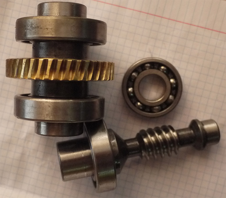
A worm gear is used in worm gearboxes. A worm gear consists of a screw, called a worm, and a worm wheel, which is a type of helical gear.
Worm gears are gear-screw. If, in a gear-screw transmission, the angles of inclination of the teeth are taken so that the gear teeth cover it around, then these teeth turn into threads, the gear gear becomes a worm, and the gear turns from a helical gear to a worm gear.
In most cases, the worm gear drive is a worm, and the follower gear is a worm wheel. Reverse transmission is often impossible - the efficiency of the worm gearbox, together with the gear ratio, causes the gearbox to self-stop.
The advantage of the worm gear in comparison with the helical gear is that the initial contact of the links occurs along the line, and not at the point. The angle of crossing of the shafts of the worm and the worm wheel can be anything, but it is usually equal to 90 °. Unlike the helical wheel, the worm wheel rim has a concave shape, which contributes to a certain worm fit and, accordingly, an increase in the area of the contact surfaces. The direction and angle of the worm wheel teeth are the same as those of the worm threads. The thread of the worm can be single or multiple, as well as right or left. The most common right-hand thread with the number of visits z1 = 1 ... 4.
There are two main types of worm gears: cylindrical, or simply worm, gears (with cylindrical worms) and globoid (with globoid worms).
Compared with ordinary gears, the gear ratio (gear ratio) of a worm gearbox can be significantly larger. So, for example, with a single worm (z1 = 1) and a worm wheel with z2 = 100, the gear ratio is u = 100. With the same gear ratio, the worm gear is much smaller than an ordinary gear transmission. The possibility of a large gear ratio with one gear level, compactness, smoothness and quiet operation - the main advantages of worm gear reducers. Due to these advantages, worm gears are widely used in hoisting machines, various machines and some other machines. The worm gear ratio is usually taken within u = 8 ... 90, but in special settings it reaches u = 1000 and more.
In the worm gear, in addition to the transmission power losses inherent in gears, there are power losses inherent in the screw pair. Consequently, the efficiency of the worm gear is much smaller, which is the main disadvantage of worm gears. The disadvantages also include the tendency of the threads of the worm and the teeth of the wheel to jam, and the need for expensive antifriction materials for the worm wheel rims. Because of these shortcomings, worm gearboxes are used much less frequently toothed and only for the transfer of small and medium power, usually up to 50 kW and less often up to 200 kW.
Due to their design, worm gear motors are characterized by smoothness and noiseless operation. The advantages of the worm gear motor can also be attributed to compactness - the worm gear motor will be significantly smaller compared to a similar gear motor with a gear drive with the same gear ratio. A characteristic feature of the worm gear motor is the property of self-retarding.
Worm gear motors have an output shaft positioned at 90 degrees, which is convenient in the case when it is not possible (for example, in size) to arrange the entire gear motor with a coaxial shaft position.