Adjustment of gearing bevel gears main gear. Adjustment of gearing of bevel gears of rear axles of tractors
BASIC ADJUSTMENTS OF THE DT-20 TRACTOR AND THE T-16 SELF-PROPELLED CHASSIS
Adjustment of gearing bevel gears main gear
DT-20 tractor. The axial clearance of the parts of the reverse mechanism on the intermediate shaft should be 0.2-0.5 mm. If the gap is greater than 0.8 mm, then replace the splined thrust washer. Spline washers are 4, 4,3, 4,7 and 5 mm thick.
The gap between the teeth of the gears of the reverse. and the gear shaft of the primary shaft should not exceed 0.2-0.4 mm for new gears and 1.5 mm for workers. Reducing the gap in the working gears is prohibited. The same clearance value at the right and left gears is set by changing the number of gaskets 8 under the flange of the cup 9 of the intermediate shaft bearing on the right side. The engagement of the bevel gears of the primary shaft and the reverse is adjusted by changing the number of shims 3 under the flange of the bearing cup 2 of the primary shaft.
Self-propelled chassis T-16. The side clearance of the bevel gears should be 0.15-0.30 mm. If the gap exceeds 0.5 mm, then you need to remove some of the shims from under the flange of the bearing cup of the input shaft. After that, the discrepancy between the rear sides of the gears should be no more than 1 mm. If this value is exceeded, then half of the removed gaskets should be placed under the flange, and from under the flange of the shaft housing of the clutch coupling remove part of the gaskets, the total thickness of which should be equal to the thickness of the gaskets newly installed under the flange of the primary shaft bearing cup.
The adjustment of the gearing of the bevel gear pair is made by longitudinal movement of the cups 5, 10, 25, which is carried out by changing the thickness of the gaskets 6, 14 and turning the round nuts.
The adjustment of the gearing of the bevel gears is made by moving them along their axes with the subsequent fixation of the wheels in the required position.
Adjustment of gearing gears can be made by shifting the gasket from under one crankcase cover under the other. With proper adjustment of the gearing, the movement of the flange of the shank around the circumference of a radius of 40 mm should be between 0 2 - 0 6 mm.
It is not recommended to adjust the gearing of gears to reduce the lateral clearance between the teeth when they are worn, as this will cause a violation of the relative position of the running-in surfaces of the teeth and may cause their breakdown. When replacing worn gears with new ones, it is necessary to adjust their mutual position with the help of shims. In this case, you must first adjust the bearings.
Adjustment of gearing gears during assembly at the factory do not produce, as the correct gearing gears provided the appropriate tolerances on the mating parts. When overhauling to compensate for the wear of the bearings, check the correctness of the gearing clutch on the paint. The adjustment is made by removing part of the gaskets from under the flange of the bearing housing of the drive pinion shaft. The lateral clearance between aubyami should be within 0 1 - 0 4 mm, which corresponds to the angular displacement of the cardan flange on the radius of the holes by 0 25 - 0 9 mm. The standard package includes gaskets with a thickness of 0 100 - 0 085; 0 25 - 0 23 and 0 80 - 0 75 mm.
The gearing of the bevel gears of the main gear is adjusted by axial movements of their shafts. Small bevel gear move, changing the number of adjusting shims installed between the shaft housing of a small bevel gear and crankcase main gear. The standard package includes gaskets with a thickness of 0 05; 0 1; 0 2; 0 5; 1 0 mm. Gaskets 0 1 and 0 5 mm set on demand.
The gearing of the bevel gears of the main gear is adjusted by axial movements of their shafts. Small bevel gear move, changing the number of adjusting shims installed between the shaft housing of a small bevel gear and crankcase main gear.
Adjusting the gear on the paint according to the nature of the contact patch is made as follows.
Adjusting the gear on the paint according to the nature of the contact patch is made as follows. The teeth of one wheel are smeared with paint and both wheels, after their adhesion, are checked for two or three turns. As a result, imprints appear on the teeth of the wheel, not smeared with paint, by which the quality of the gearing is judged. As already noted, the most favorable imprint is considered, when wheels without a load transfer efforts by a thin part of the tooth (see FIG.
| Control circuit assembly assembly bevel gears. | Types of paint prints with incorrectly meshed spur bevel gears. |
The adjustment of the engagement according to the nature of the contact patch is made as follows.
Adjustment of the gearing of the bevel gears of the main gear is carried out after installing the driven gear in the crankcase and checking the bearings. Installation of the driven bevel gears produced depending on the design of the rear axle. Before installing it from the car M-20 pre-assemble the crankcase cover and axle shrouds with bearings and seals. The outer rings of tapered roller bearings are installed in the holes of the crankcase cover until it stops at the end. Two glands are pressed into the casing of the axle shaft, their working surface is greased with grease.
Assembly gears
TO category:
Metalwork and instrumental work
Gear assembly
Assembling gears is the implementation of typical connections - keyed, splined, pin, detachable movable and stationary, threaded, etc. The assembly sequence of each node is determined by its design. Assembled by methods, methods and techniques discussed earlier, using appropriate tools, equipment and accessories.
Gear assembly includes preliminary control and preparation of transmission details; the actual assembly; checking; adjustment and running in.
The sequence and methods of making the connections are determined by the design of the product. For example, if the gear housing has a connector along the axes of the shafts, the shafts in the housing are assembled with wheels and bearings. Then install the upper part of the body and fix it. Finally, the bearing caps are assembled. In the event that there is no such connector, the assembly becomes more complicated. At first, one of the bearings is assembled on the shaft, the free end of the shaft is inserted into the housing through a bore in which the bearing assembled on the shaft is mounted. And already through a window in the case gear wheels, details of their fastening, the second bearing on the shaft are assembled. Then the shaft is mounted with bearings in the corresponding housing bores and put in place the bearing caps.
After assembly, the transmission is monitored and controlled by the radial runout. gear wheel, contact area of teeth engaging gear wheels and side clearance in the mesh. To check the contact spot one of the elements gearing (usually a smaller wheel or a worm) smeared with a thin layer of paint and slowly turn it a few turns. The displacement of the contact patch indicates a reduced or increased axial spacing, the misalignment of the axes. Depending on the degree of accuracy of the gear and its type, the contact patch should be at least 30-75% of the height of the tooth and 30-95% of the length of the tooth. Large contact areas correspond to more precise gears.
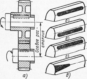
Fig. 1. Determination of the gearing defects of the cylindrical wheels by the contact patch: a is the engagement pattern, b is the normal center distance, c is the reduced center distance, g is the increased center distance, d is the misalignment of the axes
The lateral clearance in cylindrical and bevel gears is determined by a probe or by rolling a lead wire between the teeth, the diameter of which is one and a half times the allowable gap. The guaranteed side clearance in the worm gear is determined by the angle of rotation of the worm with the worm wheel attached.
Assembled gears are checked for smoothness and noise. If there are defects, adjust the transmission, and if it is impossible to eliminate the defects, they replace the corresponding parts.
Assembling a single-stage cylindrical gearbox with oblique teeth. The basic detail of the assembly unit of the gearbox is its case, which is aligned for assembly in the horizontal plane with an accuracy of 0.1 mm at a length of 1000 mm using a control ruler and level laid on the surface of the connector. As a rule, gearboxes have a plane of the connector along the axis of the shafts, which ensures good assembly conditions.
The first gearbox with the wheel and two roller bearings and a set of adjusting rings, installed between the end of the outer ring of the bearing and the fixing covers, are installed into the gearbox housing 6 first. The output ends of the shafts are sealed with cuffs.
Similarly, assemble a pinion shaft with tapered roller bearings and adjusting rings with a fixed cap; cuffed and sealed with a lid. When assembling, the planes of the case connector and the lid are coated with a “sealant” paste to ensure density; then put the bolts and taper pin.
To inspect the teeth of the gearing and oil intake during assembly, there is a viewing window in the lid that is closed by a lid. For oil filling during operation there is a hole, closed by a stopper. For circulation lubrication, a nozzle is installed (when lubricating the wheels with immersion, there is no nozzle). Oil is drained through a hole in the lower part of the body, closed by a stopper. To control the oil level is a control plug.
Breaking gears. Gear-in gears are made to correct improper touch stains, i.e., to increase the contact area along the length and height of the teeth to the size required by the technical conditions, to reduce the roughness of the working surfaces of the teeth, reduce noise and increase the durability of gears. In the process of grinding the surface of the teeth are mutually abrasive grinding pastes placed between the teeth.
For the run-in apply abrasive pastes and pastes GOI. The grain size of the paste is chosen depending on the degree of accuracy, hardness of the tooth surface and the gearing module. For the break-in, the teeth of the wheel are covered with a thin continuous layer of abrasive paste and, using an electric motor connected to the drive shaft of the gearbox, give a trial burn-in at a speed of 20–30 rpm in the range of 5–10 min. After removing the paste from several teeth, they check the condition of their working surfaces. The absence of scoring and other defects, as well as the appearance of traces of contact indicates a normal process. In the future, run-in lead with a gradual increase in braking torque on the output shaft of the gearbox.
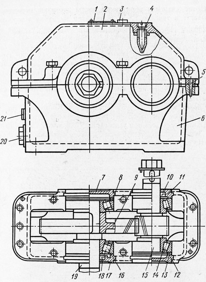
Fig. 1. Reducer cylindrical single-stage with oblique teeth
The process of breaking in every 30 minutes is interrupted in order to inspect the condition of the surfaces of the teeth, determine the size of the touch spot and replace the used paste with a new one.
After removing the abrasive paste, gears roll in for 1.5-2 hours, feeding industrial oil on the teeth, which allows you to completely remove the abrasive grain and get a smooth, shiny tooth surface that characterizes the final area of the contact patch. If a gear pair has a multiple number of teeth, then one tooth of the gear wheel and two adjacent teeth of the wheel from the ends are marked (for example, with the letter O) so that the mounted teeth will coincide during installation. For gear pairs with a non-multiple number of teeth, marking is not done, since each tooth of the wheel is added to all gear teeth.
Assembling bevel gears. Bevel gears are used to transfer rotation between shafts, the axes of which intersect at an angle (Fig. 2, a), as a rule, equal to 90 °.
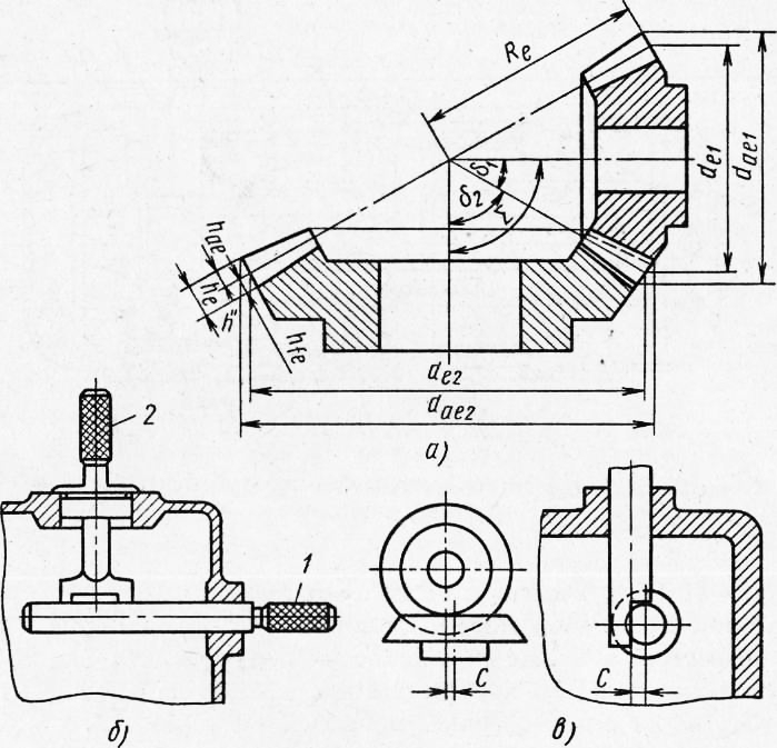
Fig. 2. Scheme of a bevel gear (a), checking the perpendicularity of the axles of the wheels (b), checking the alignment of the axles (c)
The main dimensions of the bevel gear are usually considered in the external section, where the tooth has the largest dimensions on the surface of the additional cone (outer pitch diameter de = mzl, tooth peaks diameter d = t (z + 2aS5), where 6 is the pitch cone angle - the angle between the axis a conical wheel and a dividing cone forming it, Fig. 2, a). They can be viewed in any other section (average, internal, etc.).
The requirements for bevel gears, as well as the techniques for assembling and mounting them on a shaft, are the same as for cylindrical gears.
It is advisable to fit the wheels so that the teeth come into contact with the working surface closer to the thin ends, since the thin side is more quickly mined and during loading due to the deformation of the thin end of the teeth, their fit is achieved over the entire length.
Before installing the gears check the axle angle and the displacement of the axles. The perpendicularity of the axes is checked by a cylindrical mandrel and a mandrel having two protrusions whose planes are perpendicular to the axis. The probe measures the gap between the protrusions. The alignment of the axes is checked with mandrels similar to mandrels with the ends cut to half (Fig. 2, c). When combining the mandrel probe measure the gap C between them.
The pressed-up wheels check for the crown's beating, mount the gear and achieve the coincidence of the imaginary vertices of the cones. Pre-installation done at the ends of the wheels. The gearing is controlled by displacing the gears in the axial direction, until the same lateral C „and radial clearances around the entire circumference are obtained. You can shift either one wheel or both. Found the correct position of the wheels fixed set of gaskets or adjusting rings, laid between the end of the wheel and the ledge of the shaft. In the presence of angular contact bearings with adjusting shims gearing regulate the displacement of the shaft with the wheel. In order not to disturb the gaps in the bearings, to shift the wheels from under one bearing, the spacers are removed and shifted to the opposite bearing.
The correctness of the gearing check on the paint. Paint the teeth on one wheel and roll the wheels to produce a print. When the imprint is not located in the center of the tooth, the engagement is adjusted.
If the gear wheel, which sits on axis II - II, is moved to the left - in the direction of the apex of the initial cone, the gaps in the gearing will decrease. If the side clearance cannot be measured with a feeler gauge due to the difficult approach to transmission, then thin lead plates are used, the thickness of which is 1.5 times the size of the required clearance. To do this, chalk three teeth, evenly spaced around the circumference, and insert lead plates between them. Then rotate one of the shafts. Clenching between the teeth, the plates flatten out. By measuring the thickness of each plate with a micrometer and calculating the arithmetic average of three measurements, the value of the lateral gap is obtained.
Adjusting the gear on the paint according to the nature of the contact patch is as follows. The teeth of one wheel are smeared with a thin layer of paint and both wheels are checked for 2 - 3 turns. On the teeth of a wheel that is not smeared with paint, an imprint is obtained that is used to judge the gearing. The size of the spot depends on the class of accuracy of the transfer and should be 40 - 60% of the length of the tooth and 20-25% of the height of the working part.
If the traces of paint are located tightly on one side of the tooth at the narrow end, and on the other side - at the wide end, this indicates a distortion of the gear wheels. These errors should be corrected by additional fitting operations. Transmission disassemble and check whether the gears are installed on the shafts and the position of the axes in the housing.
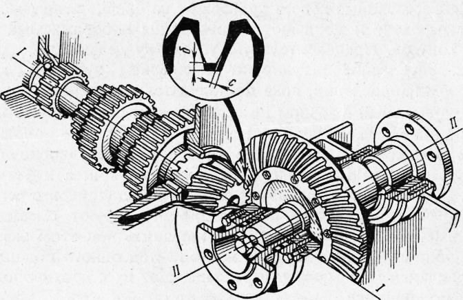
Fig. 3. Check and adjust the clearance by shifting the wheels along the axes I-I and 11-11
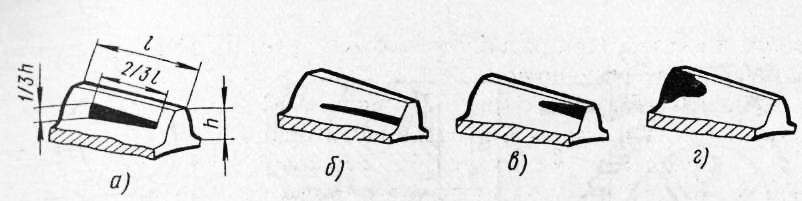
Fig. 4. Location of contact spots when checking for paint: a - correct engagement, b - insufficient clearance, c, d - irregular center angle
The required contact patch in bevel gears is obtained by running in with abrasive pastes, as for cylindrical gears.
Worm gear assembly. Worm gears are used to transmit rotation between two shafts that cross at an angle of 90 °, and to obtain a large gear ratio. Usually the transfer is carried out from the worm to the wheel. The worm gear consists of a worm 1 - a screw with a modular trapezoidal thread (profile angle 40e) and worm wheel.
Gear ratio worm gear - the ratio of the number of teeth of the wheel z2 to the number of visits of the worm zu i.e., and - z2 / zv
For worm gear GOST 2144 - 66 provides gear ratios from 8 to 80. Worm gears have a relatively low KPD.
Worms can be single-threaded and multi-threaded and be performed together with the shaft or mounted, manufactured separately and mounted on the shaft with the help of dowels.
The distance between adjacent turns of the worm - step P (Fig. 80, b). The pitch diameter of the worm is d = qm, where q is the coefficient of the diameter of the worm (q = 7.1 - 2.5).
The worm wheel has concave teeth of a spiral shape. In axial section, it has the same elements and geometrical dependencies as the cylindrical gear. The worm is made of steel 40, 45, 40X, 40XH, followed by quenching (preferably high frequency currents) or cemented steel 15X, 20X, 20HNZA, 20HF, etc. The turns of the worms are ground.
Worm wheels for increasing the efficiency of gears are made of Bronze O.FYU-1, Bron.ONF, Br.AZh9-4. Wheels of low-speed gears are made of cast iron. To save expensive bronzes, only a crown is made of them. It is pressed onto a cast-iron or steel hub and fixed with screws or bolts.
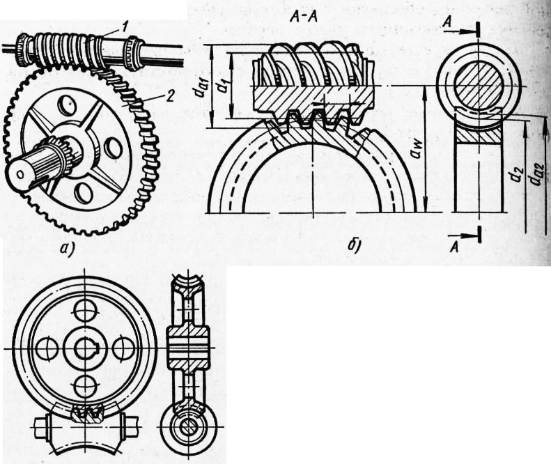
Fig. 5. Worm gear: a - general form, b - transfer elements, c - concave worm
In addition to worm gears, in which the worm has a straight line forming a dividing cylinder (archimedean worms), there are gears with involute worms (they have an involute turn profile), as well as globoid gears with concave-shaped worms.
The following technical requirements are imposed on worm gears:
1. The profile and thread pitch of the worm wheel and the worm must match.
2. The worm must be in contact with each tooth of the worm wheel for at least 2/3 of the arc length of the tooth of the worm wheel.
3. The radial and face beating of the worm wheel should not exceed the limits established for the corresponding degrees of accuracy.
4. Inter-axle distances must be in accordance with the calculated value, providing the necessary clearance set for the appropriate class of gear.
5. The axes of the intersecting shafts should be at an angle of 90 ° to each other and coincide with the corresponding axes of the sockets in the housings.
6. Assembled gears are tested at idle (or under load).
7. The magnitude of the dead stroke of the worm (the angle of rotation of the worm when the wheel is fixed) should be no higher than the established standards for the appropriate class of gear; when checking for ease of turning the worm, it is ensured that the torque is within the limits allowed by the technical requirements.
8. During the testing of the assembled gear under load, the smoothness and heating of the bearing supports is checked, which should be no higher than 323-333 K (50-60 ° C).
9. When checking the transmission should work smoothly and silently.
Worm gear assembly begins with checking the center distance of the gear housing. The method for controlling the axle spacing is shown in Fig. 6, a. In the case set control mandrel. On.one of them install a template with three tabs. The magnitude of the gap between the protrusion of the template and the mandrel determine the deviation center distance.
Ways to control axial skew (crossing angle) are shown in fig. 81.6.
1. Check the mandrels and the template, as well as the center distance. Measure the gap between the protrusions of the template and take the difference of evidence. The magnitude of the skew width of the wheel will be obtained by multiplying the difference obtained by the ratio of the dimensions of the width of the wheel to the distance between the projections.
2. On the shaft of the worm wheel or mandrel put on the lever with the indicator. Summing the indicator pin alternately to the left and right ends of the worm shaft or mandrel, the difference in the deviation is judged by the misalignment of the axes.
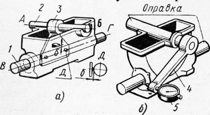
Fig. 6. Ways to control the holes in the worm gear housing: a - axle spacing, b - axes skew (crossing angle)
On the protruding ends of the worm and the wheel, the levers on the indicators are fixed, notice the position of the indicator arrow (and therefore the worm) in the initial position, and then the worm is slightly turned before the lever starts to deflect, and the angle cp (in angular seconds) is equal to the indicator reading ( the difference between the final and initial values) multiplied by L: 3600 (L is the distance from the worm axis to the indicator ball).
Normal engagement of bevel gears protects them from premature wear and breakage and reduces friction in the teeth. Such an engagement of bevel gears is correct when their axes lie in the same plane, perpendicularly to one another, and the tops of the cones coincide. To do this, bevel gears must be installed in a certain position in the rear axle housing.
As a result of the wear and tear of parts, the gear engagement may be broken. With significant wear of bearings and their mounting seats, the perpendicularity of the axles of the gears is broken or the axles may not be in the same plane; when the teeth wear out, the side clearance between the gears increases and the contact surface shifts along the height of the tooth.
In the first case, it is necessary to replace the bearings. To restore the original position of the gears by moving them in the axial direction. Compensation of wear of gear teeth by their additional movement is not allowed, since when a normal clearance is established between worn teeth, the tips of the cones will not coincide.
When assembling the rear axle, the pinion gear 28 (see the diagram of the rear axle of the “Belarus” tractor) is set so that the distance between its rear end and the geometrical axis of the differential is 130 ± 0\u003e 15 mm. This is achieved by laying under the flange of the glass of the front bearing of the primary shaft of the gearbox. The side clearance in the gear teeth in the range of 0.25 - 0.50 mm is regulated by gaskets 22 under the flanges of the right and left glasses of the bearings of the differential axis. The correctness of gearing gears check for paint: the teeth of the pinion gear cover with a thin layer of paint and turn the driven gear one turn.
An engagement is considered correct if the ink imprint is located not less than 80% of the length of the tooth of the driven gear and the middle of the imprint does not have a large displacement towards the base or the top of the tooth.
The amount of lateral clearance is determined by a lead plate rolled between the teeth at the large gear base, or by an indicator.
The correctness of the gearing and the size of the side clearance of the gears that are working are checked during the current repair of the tractor or when signs of abnormal operation appear. bevel gear. In the latter case, it is necessary to check if there are no chips, nicks and other malfunctions on the gears, whether the crown of the driven gear on the hub or the left bearing on the differential axis has weakened.
To adjust the gearing of the working gears should be only in the case when the rear axle disassembled or if the gap in the teeth exceeds 1.2 mm. The order of such adjustment is as follows: disconnect the brake rod and remove the lids of the cups; screwing the two bolts into the mounting holes of the flange, press out the right cup so that you can remove the gaskets 22; in the same way, press out the left cup by the size of the gap between the gear teeth; Using the gaskets, install an increased clearance taking into account the wear of the teeth and check the correctness of the gearing gear alignment by the nature of the print; after that, fill the bearings of the differential axle with grease and put the lids of the cups so that the grooves in them coincide with the oil supply holes in the cups.
The procedure for adjusting gearing gears
The procedure for adjusting the gearing of gears to ensure the correct contact patch is similar to that described in the design of the ZIL-431410 vehicle axle (see Table 3.1).
When checking at the manufacturer on the test bench of a selected hypoid pair to correct the contact patch to ensure silent operation, the gear can be shifted by ± 0.3 mm from the theoretical set size L = 219 mm (3.39). The sign "- + -" corresponds to the removal of the gear from the wheel axis. In accordance with the magnitude and direction of the gear shift, a deviation in millimeters from the theoretical established size with an appropriate sign “-) -" or "-" is applied on its small end. If the contact patch corresponds to the reference one at the nominal installation size, then the figure 0 is applied on the hypoid gear gear. The deviation is indicated after the set number.
After all adjustments with the support screw, it is necessary to set a gap of 0.15 ... 0.20 mm between the support pad and the hypoid gear wheel, and then fix the screw with a lock nut.
3.39. Adjusting size of hypoid gear wheels
It should be noted that in the intermediate bridge the oil remover is not installed on the support pad.
The wheel hub bearings of the drive axles are adjusted in the same way as in the front axles (see subsection “Front suspension and front non-driving axle”).
Maintenance
Maintenance of the drive axles of the ZIL-133ГЯ car, as well as the drive axles of other models, consists in monitoring the oil level and refilling it if necessary. Oil is poured through the filler holes before it emerges from the control holes located in the rear covers of the axle cases. It is recommended to drain the oil from the bridges when replacing it immediately after work. Oil level control is carried out at TO-2, change the oil at the sixth TO-2. It should be noted once again that only TM-4-18 (TSp-14gip) oil is used for bridges with a hypoid main gear. Attention must be paid to sealing the connectors in the bridges. With TO-1, it is necessary to check and tighten all the bolts and nuts, especially to pay attention to the fastening of the main gear to the crankcase of the bridge, as well as to the tightening of the bolts of fastening of the glasses and covers of the conical bearings of the gears. Loosening the bolts may result in poor contact of the gears and increased wear. Frequent loosening of the bolts, causing the need to tighten them, may indicate the appearance of an axial clearance in the bearings. In this case, it is necessary to restore the bearing adjustment.
Attention should be paid to the connection of axles with wheel hubs. Loosening the nuts of this connection can lead to cutting off the axle mounting studs.
It is also necessary to monitor the reliability of the lip seals and the purity of the breathers. Clogged air vents increase the pressure inside the crankcase and can cause oil to leak even through serviceable seals.