Organization of ship service mechanics. The whistle is placed in a special pocket, is used for audible alarm in poor visibility conditions. The sound of a whistle is heard two to three times farther than a scream, and it is easier to auditory direction finding. System h
Send your good work in the knowledge base is simple. Use the form below.
Students, graduate students, young scientists who use the knowledge base in their studies and work will be very grateful to you.
Posted on http://www.allbest.ru/
Reportpo swimmernoah practice
Plan
Section 1. Organization of service on ships of maritime transport
1.1 Basic provisions of the statute of service on transport ships
1.2 Organization of service on the ship
1.3 Responsibilities of class 2 mechanic
Section 2. The device of the ship, ship devices and life saving equipment
2.1 Purpose, technical characteristics and design of the hull
2.2 Anchor device
2.3 Mooring system
2.4 Steering gear and steering gear
2.5 Ship shafting
2.6 Ship rescue equipment
Section 3. Ship systems
3.1 Ballast-drainage system
3.2 Water extinguishing system
3.3 Seawater system
Section 4. Ship Power Plants
4.1 Safety regulations when servicing auxiliary boiler plant
4.2 Ship pumps
4.3 Air compressor
4.4 Fuel and oil separator
4.5 Bilge water separator
4.6 Water desalination plant
4.7 Responsibilities of the watch mechanic on the running mode and on the parking lots
Section 1. Organization of service on ships of maritime transport
1.1 Main provisions of the articlethat service on transport ships
The charter of the sea and river fleet defines the basis for organizing service on ships, as well as the basic duties and rights of ship crews. The requirement of the charter applies to members of the crew of ships, both when on board a ship or during the performance of official duties ashore. Violation of the requirements of the statute entails disciplinary or other statutory liability. The charter defines the basics of organizing service on ships, the basic rights and obligations of persons on the ship’s crew. The requirements of the Charter apply to all crew members and other persons temporarily on board. The captain is given the right to temporarily, in connection with production needs or in order to ensure the safety of the vessel, cargo or people, to redistribute duties between crew members on the vessel.
1.2 Organization of service on the ship
The crew consists of the captain, other officers and the crew. Ship's crew consists of deck and machine. The commanding staff includes: captain, assistant captain, chief (senior) mechanics, mechanics of all specialties and other persons occupying engineering and technical positions. The senior commanders are the captain, the chiefs of services. All crew members, depending on the functions performed, are divided into services:
* General court serviceprovides safe navigation, technical operation of the ship's hull, deck devices and mechanisms, organization of service and collective feeding of the crew and passengers. General ship services are headed by a senior mate.
* Ship Mechanical Serviceprovides technical operation of ship machinery and mechanisms, technological units, installations and equipment, deck and field mechanisms. The ship mechanical service is headed by the chief (senior) mechanic.
Ship schedules
1. All technical means, equipment and equipment, as well as the ship’s premises are distributed to the head of certain members of the ship’s crew in order to ensure their technical maintenance, readiness for action and safety.
2. For the organization of the service on the ship the following schedules are drawn up: the schedule for the institutions; watch schedule; ship alert schedules; schedule for mooring operations; schedule for residential premises. Other schedules may be drawn up on board to improve the organization of the ship service. Ship schedules are approved by the captain.
Each crew member must:
* Know the device of the vessel and its superintendence, the rules of technical operation of mechanisms, systems and devices.
* To observe the internal schedule established on the vessel, to carry out orders of the captain and persons of commanding staff on subordination.
* To know and carry out their duties to ensure the survivability of the vessel, to be able to use, in accordance with its duties, ship technical means of fighting for survivability, rescue and fire fighting equipment and equipment, to be able to use life-saving equipment.
* Know and comply with safety regulations, fire safety, health regulations, environmental protection rules, border and customs regulations, the provisions of the Charter.
* Any person on the ship using ship technical equipment or consumer services, regardless of whether he has received permission for such use or not, is fully responsible for their correct use.
* Any crew member who detects abnormal work or the unsatisfactory condition of the ship’s technical equipment is required to immediately report this to the watchman assistant to the captain (watchman mechanic), taking all possible measures to eliminate them.
* Whenever a danger threatens the vessel, people, cargo, and technical equipment, any person on board must immediately report this to the watch officer of the captain (watch mechanic) and at the same time take steps to eliminate it.
* All crew members are required to perform emergency and emergency work announced by the captain.
* None of the crew members has the right to leave the vessel before the end of the flight without the permission of the captain.
* Members of the ship’s crew may descend from the ship only with the permission of their immediate supervisors. When leaving the vessel, as well as upon arrival on the vessel, the crew members are obliged to notify the watch officer of the watch.
* Members of the crew, as well as other persons staying on board, are not allowed to start work and to intervene on the watch and intoxicated state, or if there are signs of illness. A person who has appeared in a state of intoxication is subject to immediate suspension from work or watch.
1.3 Responsibilities minder 2 classa
* Class II motorist must:
To know the structure of the main and auxiliary mechanisms, the purpose and location of the pipelines and valves serving them;
To be able to maintain the main and auxiliary mechanisms and technical means to ensure their work;
To be able to maintain auxiliary boilers and technical means to ensure their work;
Know the location of storage facilities for rescue equipment, fire extinguishing equipment and know how to use them.
* Motorist class 2 must:
To take part in the maintenance and repair of all ship technical equipment;
Follow the rules of technical operation of ship technical equipment;
Safety and fire safety regulations; keep watch in accordance with the ship's schedule.
* A motorist of class 2 may be engaged at the direction of a senior mechanic to ship work outside his regular duties, including mooring operations and securing cargo, after appropriate training, obtaining a qualification certificate, briefing on safety regulations at the workplace and issuing admission to these works by order of the captain.
Before intercessionm on watch2 class must:
1. To get acquainted with the state and mode of operation of the serviced hardware.
2. To receive from the mechanic, who passes the watch, information on the state of the technical equipment being serviced and orders sent by the watch.
3. Report to the watch mechanic about the readiness to take the watch. With the permission of the watch mechanic, to make the reception and transmission of the watch.
During the watch, the motor mechanic is obliged to:
1. To be at his post, to monitor the work of the existing technical equipment of the mechanical installation assigned to him and to manage them.
2. Follow the maintenance instructions of the mechanical installation hardware.
3. Follow the instructions of the watch mechanic to ensure the uninterrupted operation of mechanisms on the specified modes of operation and other orders.
4. Comply with safety and fire safety regulations.
5. Immediately report to the watch mechanic about the noticed malfunctions in the work of technical means, take measures to eliminate them.
6. Maintain cleanliness and order in the engine room.
7. Know the types of alarms and their actions in accordance with the ship's schedule.
8. To be able to manage technical equipment and electrical equipment under the guidance of the watch mechanic.
Section 2. Ship device, ship devices and rescue
facilities
2.1 Purpose, technical characteristics and device
ship hull
Housing - the main part of any vessel, consisting of a set (frame) and plating. The set is a combination of longitudinal and transverse connections, providing the body with rigidity and giving it the appropriate shape.
Shipbuilding steel was used as a material for the hull, manufactured under the supervision of the register and in accordance with the requirements of the register rules. Carbon shipbuilding steels, low-alloyed high-strength steel of category A32 and D32 with a thickness of 8 ... 50 mm inclusive with a yield strength of 315 MPa for individual structures are used as the material of the main body (sheets, strip, welded profile).
For a set of hull and felling applied:
* rolled asymmetrical strip-shaped carbon-steel shipbuilding steel of nominal strength category A from No. 8 to No. 16 inclusive with a yield strength of 255 MPa and increased strength of 315 MPa.
* welded T-profiles made of sheet steel or strip steel category A32 and D32.
The body has a fully welded construction. Welded joints are made using semi-automatic and manual welding.
Welding unilateral and intermittent seams only in cases permitted by the classification society. The welded joints of the main hull structures are tested by non-destructive radiographic and ultrasonic testing methods in accordance with the welded joint testing scheme approved by the classification society.
The upper deck is made parallel to the main plane and tilted on all open parts. The board is made according to the transverse set system with the frames of the rolled section stringers. The transverse bulkheads are made flat with vertical posts of the rolled profile. Around the perimeter of the upper deck is a bulwark with a slope inward.
The freshwater and fuel tankers are located in the aft part of the hull and in the MKO. In the region of the ICE, tanks are limited to longitudinal bulkheads.
In the plane of the stringers, the necessary drainage holes are provided in the set of tanks, ensuring the smooth movement of fluid and air.
2.2 Anchore device
The anchor allows you to hold the ship in a certain position, opposing external forces in the open sea, such as wind, sea waves, current, etc.
Most ships are anchored when they are on the roads and waiting for the entrance to the harbor, as well as in emergency situations when, for example, the ship is threatened with stranded.
Anchor device includes anchor, anchor chain and anchor spire, or anchor winch.
Fig. 2.1 - Anchoring and dismounting:
and - the anchor slides on a ground; b - the anchor is hooked; s - anchor
buries; d - anchor chain tensioned; e - anchor chain pulls out
ground anchor; f - anchor rises
The anchor chain connects the anchor immersed on the seabed with the vessel, so it must take in all external forces (wind pressure, wave impacts, etc.) affecting the vessel. The length of the chain depends on the type and length of the vessel. It is much greater than the depth of the sea at the berth, since the chain must connect the vessel with the anchor so that the force acting on the anchor has a horizontal direction. Due to this, the paws of the anchor burrow into the ground.
Fig. 2.2 - Anchor chain:
a - bow anchor chain (with anchor bracket); b - intermediate
bow; c - the root of the bow; d - swivel; e is a long link;
f is a large link; g - ordinary link; h - link with spacer;
i - end bracket
The anchor chain consists of separate links; several interconnected links form a bow. Separate bows are connected by connecting links. The anchor and anchor chain are connected to each other by an anchor bracket with a swivel, allowing the chain to rotate around its axis. The chain passes through a recess in the board at the doorway for the anchor, through a stop that prevents the spontaneous removal of the chain, and is wound on chain sprocket anchor winch. The other end of the anchor chain is located in the chain box and is attached to the vessel by means of a cramp.
Fig. 2.3 - Bow anchor:
1 - anchor winch (windlass); 2 - stopper for the anchor chain; 3 - pipe
anchor hawse; 4 - anchor; 5 - anchor niche; 6 - chain box;
7 - device for fastening the anchor chain; 8 - chain pipe
Anchor device is located in the bow of the vessel. The anchor winch is also installed there. The main part of the winch is a chain sprocket, which allows lifting the armature with a chain, and during winding the chain links may lie on the chain sprocket on both sides. In addition to the chain sprocket, the anchor winch also has mooring drums (turachki) for winding mooring lines. The bow anchor device includes two anchors located on the sides of the vessel. Because of the limited area for placement as an anchor winch is used in the anchor spire. It is a drum with a vertical axis of rotation towering above the deck. The drum serving as a winch has a chain sprocket at the bottom. It is driven by an electric motor mounted in a drum.
2.3 Mooring device
The mooring device serves to moor the vessel to the berth while it is moored in the port or at the shipyard. The vessel is moored to the coast with the help of mooring lines, which are pulled from the vessel to the coast diagonally. Currently produced from various synthetic materials.
Fig. 2.4 - Towing and docking device ( general form):
1 - feed longitudinal moorings; 2 - nasal longitudinal
moorings; 3 - aft clamping mooring; 4 - nasal spring;
5 - fodder spring; 6 - pile bar; 7 - bollard; 8 - towing
bollards; 9 - mooring spire; 10 - mooring pile plate with
three rolls; 11 - ordinary bar; 12 - mooring
hawse; 13 - mooring lines
Mooring ropes are thrown onto the wharf from a vessel approaching the shore. There are braided loops at their ends, which are put on the mooring lines located on the shore of the port or shipyards. The free end of the mooring cable is laid on the side turachku anchor winch or drum anchor spire (mooring spire), and the vessel is pulled to the shore. At the end of the mooring ropes are laid around the mooring bollards and secure.
Fig. 2.5 - Clues, bale bars and bollards:
a - mooring bridle; b - moor breech; c - duck; d - ordinary
kipovy level with the directing roller; e - double bollard;
f - double cross bollard
2.4 Steering device and steering machine
With the help of the steering device, you can change the direction of the ship or keep it at a given course. In the latter case, the task of the steering device is to counteract external forces, such as wind or current, which can lead to the deviation of the vessel from a given course.
Characteristic
Nominal torque on the bullet when the rudder overlaps - 16
at a nominal angle of 35 ° on each side, kN · m
Time of rudder shifting from 35 ° of one side to 30 ° of another side with a load of no more than 28
Power of the electric motor of the pump unit, kW - 3
Pump unit size, mm, L a H B a H H a - 660Ч505Ч675
Force on the steering wheel when the steering wheel is placed at a nominal angle of 15 ° on each side, 160 N, not more
Diameter D p 140; Height H p 180
Dimension of the power drive, mm, LЧBЧH - 1180Ч510Ч675
Steering machine weight, kg - no more than 800
1 - steering car; 2 - steering pin; 3 - semi-balance steering;
4 - steering wheel
When the steering wheel rotates on the bridge, the telemotor sensor is activated. The oil flowing under pressure in the pipeline causes the telemotor receiver to move, causing the steering pump to move in the corresponding direction.
2.5 Ship shaft
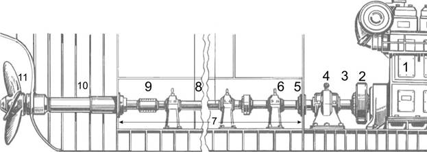
A device connecting the main ship engine with a propulsion unit. Designed to transmit torque from the main engine to the propeller, as well as to perceive the stop created by the propeller and transfer it to the ship’s hull. Shaft consists of propeller, intermediate and thrust rollers, support and thrust bearings, stern shaft, shaft swivel, brake and other devices that ensure the operation of the shaft duct. The propeller shaft is designed for fastening the propeller, and the bearings of the stern gear are its supports. The thrust shaft transmits the stop created by the propeller, thrust bearing rigidly connected to the hull. Intermediate shafts are installed between the propeller and thrust shafts to facilitate the manufacture and installation of shafting. Their bearings are thrust bearings. Shafts are usually hollow, which allows reducing their mass and provides the best conditions for heat treatment. The connection of the shafts between themselves is carried out with the help of flanges and connecting bolts or by means of removable steel cylindrical couplings. The length is 20 m.
Fig. 2.7 - Ship shafting:
1 - DG; 2 - flywheel; 3 - thrust shaft; 4 - thrust bearing;
5 - bulkhead gland; 6 - thrust bearing; 7 - corridor
propeller shaft; 8 - intermediate shaft line; 9 - half coupling;
10 - stern tube device; 11 - propeller
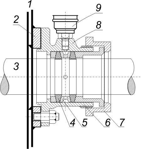
Deadwood device - It serves to support the propeller shaft (or intermediate) and seal the point of exit of the latter from the hull. It contains a stern tube with a stern shaft placed inside it, and inside the tube there are two bearings with water lubrication, the liners of which are formed by slats located along the axis of the shaft, characterized in that it is provided with a hull tube fixed in the hull of the vessel. said stern tube, and at least two elastic elements that are in contact with the stern tube, each of the elastic elements having an internal cavity communicated with the system working medium, and is fixed to the housing pipe, wherein the pipe mounted in the body active radial magnetic bearings with automatic regulation system working gaps which face the stern tube and the end faces of the stern tube and the housing are provided with tapered elements corresponding to each other. In places where the shaft passes through watertight bulkheads, bulkhead seals are installed.
Fig. 2.8 - Bulkhead seal: 1 - bulkhead; 2 - Fatty; 3 - shaft;
4 - stuffing box; 5 - bronze ring; 6 - pressure sleeve;
7 - pressure ring; 8 - housing; 9 - oiler
2.6 Ship Rescue Equipment
Rescue equipment is a set of devices, mechanisms and structures necessary for training and for saving the crew and passengers in the event of the death of the vessel.
Requirements governing ship rescue devices are specified in the following documents:
* International Convention for the Safety of Human Life at Sea, 1974 (SOLAS-74), chapter III "Rescue equipment and devices";
* International Code for Life Saving (LSA Code);
Rescue boat open. It is made of fiberglass or metal alloys, rarely of wood. The length of open lifeboats ranges from 7.3 to 11.3 m. Capacity - from 37 to 145 people.
To increase the buoyancy of open boats are equipped with built-in or removable hermetic air boxes of stainless materials. The volume of the air boxes of the boat flooded along the airframe allows it to be held on the surface of the water with full load - passengers, emergency stock, etc.
Open boats are driven by the engine or manually by the passengers through a crank mechanism. All open boats have awnings from a two-layer (with an air gap) waterproof material that protects passengers from exposure to cold and weather.
Along the sides of the boat rescue rails are stretched with wooden or plastic handles, which a person in the water can grasp.
Rescue boat closed. It is made of fiberglass or metal alloys. The length 66 of the local lifeboat is 8.5 m, and the maximum width is 3.05 m, the height from the bottom to the ceiling of the hard awning is 2.35 m. The fuel reserve is designed for 24 hours of continuous operation.
When tipping the boat returns to its normal position. In order to avoid injuries in a strong storm, passengers should fasten their seat belts with special seat belts. Passengers are taken to the boat (including those injured on stretchers) through special hatches and from the water.
In addition to the described, there are closed boats of smaller capacity, as well as special, for example, tanker boats.
Liferafts rigid design. Most often used on ships of the river fleet. The shell of hard rafts is made of fiberglass or aluminum-magnesium alloy. The buoyancy chambers are divided into insulated compartments, which are filled with foam inside, which allows the raft to stay on the water surface even if the shell is damaged.
Most of the rafts are supplied with a removable wind and rain protective awning, installed in the working position using arcs on either side of the raft. The hard metal raft of the ATP 12, with dimensions of 1.5 by 1.8 m, has a total weight of 180 kg (with equipment and supplies). It is designed to save 12 people - two people are placed on top and 10 in the water are held behind a circular line.
The plastic hard rafts of the SPP 6 and SPP 12 are equipped with a wind and weather protective awning and, accordingly, can hold 6 and 12 passengers. The heaviest of hard rafts is SPA 12, its total weight is 280 kg.
Inflatable rafts. If necessary, any of the rafts can take the crew, twice the standard. An inflatable liferaft raft consists of an oval-shaped main buoyancy chamber divided in the middle into two autonomous sections of equal size.
An inflatable bottom is attached to the bottom of the buoyancy chamber. Two beams in the form of inflatable arcs support a protective awning consisting of two layers of waterproof material. The air gap formed between the layers of fabric increases the insulating properties of the awning, reduces the dampening of the material. The raft has two inlets, which, if necessary, can be closed using double curtains.
The raft from the outer and inner sides is painted in bright orange color. On the inner side of the tent are placed: instructions for the primary servicing of the raft, the layout of the valves (safety, blowing and blowing) and Morse code signs.
Purpose of supplies.
1. Water-filled battery. To activate the battery, it is necessary to pull out the insulating plugs from its case. The battery provides a search signal fire - 20 hours.
2. Valves blowing - 4 pcs. For swapping the raft with foot pump, hand fur or mouth. Located on the buoyancy chamber near the arcs and on the bottom of the raft.
3. Handles on the bottom serve to return the inverted raft to its normal position. A carbon dioxide bottle is used as a footrest.
4. Manual fur is designed for swapping and complete blowing of the raft.
5. Container with supplies. Attached to the buoyancy chamber between the awning arches.
6. Signal search fire. Located on the outside of the arc tent. The 2.5 volt bulb is protected by a clear plastic cap. Visibility limit 1-4 km. The light bulb is connected with a soft wire with a water-filled battery.
7. A set of indoor lighting. Located on the arc near the entrance from the inside. It consists of a light bulb in a protective cap, mounted in a rubber, hermetically sealed bag, inside which is a water-filled battery. Outboard water is poured into the bag, after which the light begins to shine.
8. Metal plugs (7 pcs.) Are designed to blow the raft. They are located on the buoyancy chamber at the entrances, on the central bank, the bottom and the awning arches from the outside.
9. Tow line ten-meter long. Stored in the bay on camera buoyancy. When towing attached to the rings on the outer ladder.
10. Water tanks - sloping grooves on the outer tent of the raft, converging in the center - are designed to collect rainwater. Drain pipes of water tanks with stoppers are inserted inside the raft.
11. Bag with oars and other equipment. Attached to the buoyancy chamber between the awning arches.
12. Start line. When the tension actuates the mechanism of the automatic gas filling of the raft. He also performs the functions of a safety line, holding the inflated raft in close proximity to the emergency vessel.
13. Cylinder with carbon dioxide. Attached to the bottom of the raft with a special lacing.
14. Safety valves (4 pcs.). They are used to relieve excess pressure in the cylinders when the raft is automatically inflated or overheated in the sun. Located on the buoyancy chamber and awning arcs.
15. Scoop with foam rubber. Used to dry the internal volumes of the raft.
16. Ballast pockets. These are rectangular-shaped rubber bags attached to the bottom of the raft from the bottom. When filled with seawater, they increase the stability of the raft on the waves, reduce wind and wave drift. If necessary, they can be removed by pulling the special streamers attached to the entrances.
17. The cutting end with a rubber ring. Fixed at one of the entrances. Designed to feed assistance and pull the victim to the raft. The throwing end and the ring must have independent buoyancy.
18. Internal ladder. Facilitates the rise of man from the water. Increases the longitudinal rigidity of the raft.
19. Outdoor railing. Designed to keep afloat people in the water.
20. Outdoor ladder. Facilitates the rise of man from the water. Floating anchors, towing lines, etc. are attached to the ramp.
21. Floating anchor (2 pieces). One inside and one outside the raft. Designed to reduce wind and wave drift, increase the stability of the raft.
Inflatable rafts have an oval shape and are available mainly of two types: six-seater (PSN 6) and ten-seater (PSN 10). In addition, on the Russian ships are used round and multi-faceted rafts imported. PSN are stored in folded form in a special plastic container box. In the event of an accident, the raft is dumped into the water, where it is put into working condition within a few minutes using a gas-filling mechanism.
Due to the low weight and the lack of special devices for launching, the use of rafts is permissible even in cases when the boats cannot be used.
Individual means of salvation
That is, funds intended for the salvation of one person who fell into the water. These include: life jackets, bibs, circles and various life suits. The most common are life jackets. The number of vests on a ship is determined by the total number of its crew and passengers, plus five percent of the required reserve. In addition, the vessel must have at least two dozen children's life jackets with the well readable inscription “For children”. Life jackets are placed in easily accessible, well-known and clearly marked places. For passengers - in the cabin. There are several types of life jackets, but the requirements for all are almost the same. A life jacket must: quickly put on and be fixed on the body with one or two simple operations. If necessary, it should also be removed quickly. Incorrect or delayed donning of a life jacket should be excluded; have two or three buoyancy chambers isolated from each other, each of which is capable of holding a person on the surface of the water. The body of the victim, dressed in a life jacket, should be close to the horizontal (in most modern life jackets up to 50 degrees deviation from the vertical), since the vertical position would increase the cooling of the legs - the deeper, the colder the water. The head of the victim should be slightly tilted back, while his mouth is 12 cm from the surface of the water. When wearing a vest, the body acquires such a position in water in 4-5 seconds, even if the victim is unconscious. It is necessary that the back of the head does not sink into the water, since its cooling can lead to a violation of the thermoregulation of the whole organism. In inflatable life jackets, the filling of internal volumes with air (or safe gas) is performed automatically in 2-3 seconds using a special gas-filling mechanism. To maintain a predetermined pressure in the buoyancy chambers, a valve of the working blower is provided. To facilitate the search for the victim, the life jacket is supplied with sound and light alarm means. A life vest should not hamper movements and cause harm to a person when jumping into the water from a height of up to 4 - 5 meters. The material from which the life jacket is made is incombustible and insensitive to the action of petroleum products. Passengers most often deal with a bib rescue inflatable (HCH).
Chest Rescue Inflatable is made of orange rubberized fabric. Worn over the head, covering her from behind like a collar. The main internal volume of the bib is located on the chest, which ensures the correct position of the human body in the water. Bib weight with a bag and belts 1.3 kg, positive buoyancy 16-18 kg.
Details of the vest:
1. Valve blowing in the form of a conventional tube is designed to bring the vest into the working position when there is a malfunction in the gas filling system and to maintain a given pressure in the buoyancy chambers.
2. The lifting belt is looped. Designed to lift a person out of the water. The loop of the belt is fastened to the outer surface of the bib with the help of a button that opens easily when lifting the sinking.
3. Emergency signal fire facilitates the search for a person on the water at night. Consists of a water-filled battery "Beacon" and 2.5 volt light bulbs, protected by a transparent cap. The electrical circuit is activated within 2 to 10 minutes. (depending on water temperature). The duration of the light bulb is 11 hours.
4. The whistle is placed in a special pocket, is used for audible alarm in poor visibility conditions. The sound of a whistle is heard two to three times farther than a scream, and it is easier to auditory direction finding.
5. The automatic gas filling mechanism consists of a canister with a capacity of 44 cubic meters. cm, filled with liquid carbon dioxide under pressure up to 200 atm., and a special starting head. When you pull the head gas begins to flow into the camera buoyancy. Within 2 - 3 seconds the vest takes the specified shape.
The gas filling mechanism cannot be activated if the vest was previously inflated through the operating valve. Excessive pressure leads to damage to the vest, because it does not provide a safety valve.
6. Hemp Shtert allows the victim to become attached to a floating object or to communicate with another victim. The lap and leg belts are designed to fix the vest on the body and relieve the dynamic loads that occur when a person jumps into the water.
Lifebuoys. Currently produced from various grades of foam, cork, foam polystyrene and other floating materials. The outer diameter of the lifebuoy should be no more than 800 mm, the inner diameter - not less than 400 mm.
The buoyancy of a circle of 14.5 kg is retained during the day in water. The circle must withstand a blow when dropping from a height of three meters with an edge on solid ground or flat on the water from a ten-meter height. And should not light up in an open flame for two or three seconds.
Lifebuoys are placed so that they can be easily and quickly removed. On the ships of the navy every second round is supplied with emergency signal light. The rescue line 28 meters long is attached to some circles.
Rescue free fall boats
The hull of the boat has a more durable design and well-streamlined smooth contours that prevent a strong blow when the boat enters the water. Since an overload occurs when hitting the water, special chairs are installed in the boat with shock-absorbing pads. Boats provide reliable protection in all weather conditions. Body material - fire resistant polyester fiberglass. Before the descent of the boat from the ramp-slip house, all people in the boat must secure themselves with safety belts with quick-release buckle and a special head lock. Of great importance for the safe perception of dynamic loads is the correct body position in the chair, which must be worked out in training - during training boat alarms.
Free-fall boats guarantee the safety of people at a distance of 20 m from the landing platform to the water surface.
Free-fall boats are considered the most reliable means of rescue, ensuring the evacuation of people from a sinking ship in all weather conditions.
Section 3. Ship Systems
3.1 Ballast-drainage system
transport vessel minder hull
Ballast-drainage system is designed for:
* movement of ballast water (outboard water) into and out of the ballast tank in order to change the draft and trim of the vessel;
* removal of small masses of water from the ship’s premises, appearing as a result of daily operation;
* draining the chain box.
Ballast is taken in forepick and afterpeak, in double bottoms and side tanks. Fuel tanks and temporary dry cargo holds can be used as ballast tanks. The ballast system is centralized: the tanks are filled and drained by the same pipeline. Water intake is carried out through the bottom or onboard Kingston. The ships are equipped with an automated ballast system.
The drainage system is designed to remove small amounts of water from the compartments of the vessel, where it systematically falls. The stationary system is equipped with machine-boiler rooms, dry cargo holds, cofferdam, propeller shaft corridors. The premises of cargo pumps and the bow compartments of liquid ships are equipped with their own drainage systems. Each ship must have at least two, and a passenger must have at least three autonomous, self-priming, mechanically driven self-draining pumps. A simplified diagram of the drainage system is shown in the figure below. Water collected in the bottom of the vessel is sucked through the filter and valve box and is drained overboard by a drainage pump. Since bilge water often contains oil-containing impurities (especially in the engine room area), it is passed through an oil separator, which is designed to separate the oil and oil-containing particles and direct these impurities to special tanks.
Fig. 3.1 - Drainage system:
1 - suction mesh; 2 - valve box; 3 - drainage
pump; 4 - oil separator
3.2 Fire Extinguishing System
A water fire extinguishing system in which water is supplied by a centrifugal pump to a fire main under a pressure of 8-12 kg / cm² to fire hydrants, to which fire hoses are attached. There are two main fire pumps and one emergency fire pump with its own kingstone.
The water spray system is designed to extinguish a fire with finely sprayed water. On the pipes of the system there are sprayers that create a water curtain.
3.3 Seawater system
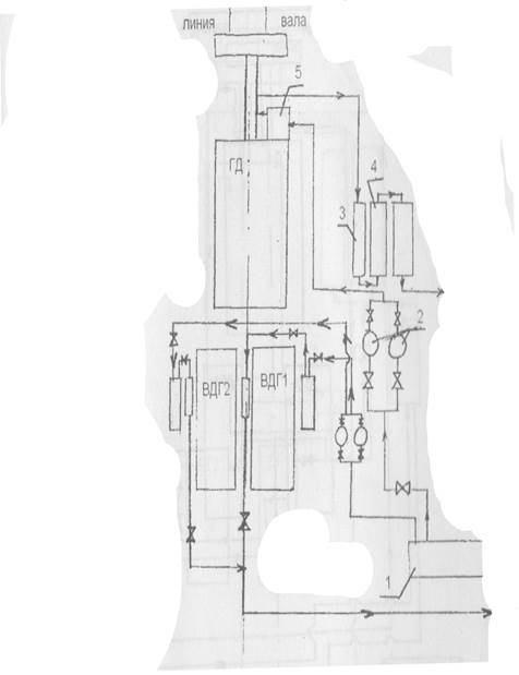
Fig. 3.2 - Seawater system:
1 - Kingston; 2 - Seawater pumps; 3 - Refrigeration Refrigerator
oils; 4 - Refrigerator fresh water cooling; 5 - Refrigerator
air cooling
Section 4. Ship Power Plants
4.1 Maintenance safety guidelines
againpowerful boiler plant
Safety regulations place high demands on personnel serving the boiler.
Persons who have reached the age of 18 years, have passed a medical examination and have a certificate for the right to serve steam boilers are allowed to work in the boiler department. During the watch they must wear workwear and safety shoes. KO staff must maintain cleanliness and order. KO flooring should be made of corrugated steel sheets, always firmly fixed, and all the cutouts in them should be closed. Oil or fuel oil spilled onto the deck should be removed immediately. Technical operation of the existing boiler should be carried out in compliance with the rules of technical operation and manufacturer's instructions. Preparation of the boiler for action should be started by inspecting all elements of the boiler and the combustion chamber in order to make sure that there are no damages.
To remove an explosive gas-air mixture, the firebox must be ventilated for at least 3 minutes.
When taking the boiler out of the action for inspection and work inside it, it is necessary to reliably disconnect it from the existing boiler, for which you should install separator plugs between the flanges of all the steam pipelines and pipelines attached to the boiler. The boiler is opened only under the direction of the responsible person.
It is forbidden to: tighten the nuts on the elements of the boilers and steam lines under pressure; perform repair work with blows and drilling; open hatches and manholes on the boiler, not disconnected from the existing boilers; penetrate the boiler if there are no plugs, locks on the isolation valves and posters "People in the boiler" on all pipes connecting it with other boilers; use electric lamps with voltage above 24V in a steam-water collector or boiler furnace; work in the internal space of the boiler at a temperature above 50 ° С without prior ventilation, without a watch on duty at the hatch of the boiler, which monitors those who work inside.
All repairs should be done with the participation and under the guidance of the mechanic responsible for the condition of the boiler. The boiler must not be put into operation if it is detected: flow in collectors, chambers or pipes; malfunction of nutrients, the absence or malfunction of at least one safety valve, water metering device or pressure gauge; malfunction of the valve of the lower blowing, as well as if the number of pipes shut off exceeds 10% of their total number. To protect against burns and reduce heat loss of the boiler, chimneys and steam lines must be insulated. The temperature on the surface of the insulation should be no more than 60 ° C. It is necessary to strictly monitor the density of fuel pipelines, valves, pumps, keep bilge clean and dry, to prevent accumulations of fuel oil in the furnace and under the pumps. The boiler room must be equipped with fire-fighting equipment.
4.2 Ship pumps
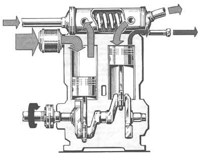
Pumps are the mechanisms by which liquids are transported or pumped from a room with less pressure to a room with more pressure. Depending on the principle of action, there are volumetric (piston, gear, screw), centrifugal (blade) and jet pumps. On ships, pumps are divided according to their purpose: bilge, ballast, nutritious for oil and cooling water, fire, pressure, etc. Volumetric pumps are used to periodically pump individual amounts of liquid from the suction chamber into the compression chamber. The simplest volumetric pump is a piston. The principle of operation of such a double-acting pump is shown in the figure below.
Fig. 4.1 - The principle of operation of a double-acting piston pump:
1 - the piston; 2-5 - valves; 6 - suction pipe; 7 - pressure
trumpet
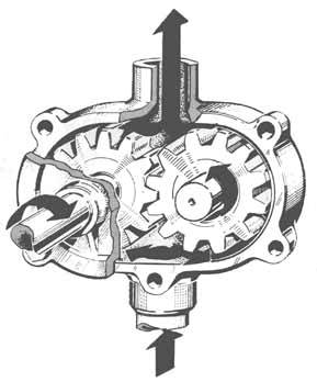
Another very common type of displacement pump is gear. The feed element consists of two gears placed in an airtight housing. One of the gears is driven, for example, by an electric motor. When the wheels rotate, the teeth protruding from the ring gear cause an increase in volume in the pump, due to which the liquid is sucked in by the lower inlet nozzle. Separate quantities of the incoming liquid are successively accumulated in the intermediate space between gear wheels and are fed between the pump casing and the wheels to their outside. Finally, the fluid enters the compression chamber. Due to the consistent entry of the wheels into the ring gear, the fluid is squeezed into the discharge port. Gear pumps are used on vessels to pump out viscous liquids with good lubricating properties, such as oil, fuel, etc.
Screw pumps also belong to the group of volumetric pumps. Liquid from the intake manifold enters the intermediate spaces between the screws, which are also called cameras and are located between the lead screw connected directly to the engine and the follower. After turning the screws at a certain angle, the liquid in the chamber is locked; then it goes up along the screws and from there it is injected into the pressure pipeline. If the pressure in the compression chamber is too high, the safety valve opens and the fluid flows back into the inlet chamber.
Fig. 4.2 - The principle of the screw pump:
1 - drive shaft; 2 - driven screws; 3 - safety
flow valve
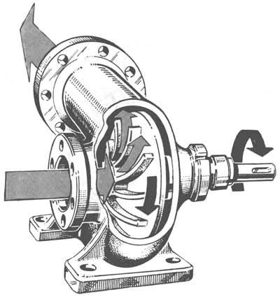
The principle of operation of the centrifugal pump is shown in the figure below. A characteristic feature of these pumps is a continuous flow of fluid. The working body of the pump, the rotor with blades, is mounted on a rotating shaft of the pump, which is most often connected directly to the drive motor. The blades of the rotating rotor transfer the energy of the engine fluid flowing through the pump, creating pressure, under the influence of which the fluid flows from the entrance to the exit. Centrifugal pumps are commonly used in ship power plants. They have a different design depending on the power. Thus, the power of injection pumps for tankers reaches several thousand tons of fluid per hour. If the pumped liquid (for example, water in fire pumps or feed pumps of steam generators) requires a higher pressure, use multistage pumps. The principle of their operation is that water, which has reached a certain pressure and leaves the first stage, flows to the next-stage suction nozzle, where the pressure rises again.
4.3 Air compressor
Compressors are machines by which gases are compressed from a low inlet pressure to a high outlet pressure. The ratio of these two pressures is the compression ratio. The simplest and most often used on ships compressor is a piston. By the principle of action it is identical to the diesel engine discussed above. As the gas temperature rises during the compression process, a compression ratio in the cylinder of the compressor can only be obtained within six to eight. A further increase in the degree of compression leads to an increase in temperature, which has a detrimental effect on the compressor. If it is necessary to obtain a higher pressure (for example, to start the main engine, an air pressure of 2.9 MPa is required), use multistage compressors. Air of atmospheric pressure (0.59 MPa) is sucked into a high-pressure cylinder with a smaller working volume than in a low-pressure cylinder, since the amount of air decreases due to compression in the low-pressure cylinder and cooling in the cooler. In the high pressure cylinder, you can again increase the air pressure six times. The final air pressure will then be 3.5 MPa.
4.4 Fuel and oil separator
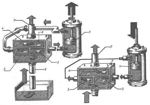
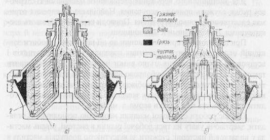
Separators installed on ships are designed to clean fuel and oil from mechanical impurities and water. The separation of mechanical impurities and water, as heavier particles, occurs in centrifugal separators under the action of centrifugal forces arising from the rotating movement of fuel or oil. On sea vessels, centrifugal separators of disc (disc) type are self-cleaning or with manual cleaning installed. The separation of dirt and mechanical impurities from the fuel is called clarification (clarification), the separation of water - purification (purification).
Watered and contaminated fuels are cleaned using a combined purification. For this purpose, two separators are installed on ships, one of which works in the mode of clarification, the other in the mode of purification. Separation of oil and separators for it are no different from the fuel separators and in the presence of a connecting system can be interchanged. On seagoing vessels, disk separators of the type NCS, Laval, Titan, Westfalia and other foreign firms are installed.
The assembly of drums for clarification and the assembly for purification differ from each other.
Fig. 4.3 - a - for clarification, b - for purification;
1 - a plate without a hole, 2 - mud space, 3 - a plate with
holes.
The rotary separator drum, assembled as a clarifier (Fig. A), receives fuel through the central channel in the lower part of the drum, is thrown to the walls, passes through the gaps between the plates and is discharged through the ventilation openings (shown in the figure with arrows). Mechanical impurities and dirt are deposited on the walls of the drum and on the surfaces of the plates under the action of centrifugal forces. The sediment from the walls of the drum and from the plates is removed manually when disassembling the separator.
The method of clarification is used when there is a significant amount of mechanical impurities and a small amount of water in the fuel. Water, leans back together with mechanical impurities, fills the entire mud space 2 and forms a hydraulic valve, which will block the flow of fuel between the plate gaps. Fuel entering the drum in a continuous stream will begin to pour out of the overflow pipe. In this case, the separator is stopped and the drum is cleaned. During clarification, the separator is started with a dry drum, and when it develops the necessary revs (8-10 thousand rpm), it is gradually filled with fuel.
For the separation of flooded (up to 3% and more water) fuel separator drum is collected as purifier (fig. B). To do this, install the bottom plate 3 with holes. When the separator is working according to the purification method, the drum is filled with warm water, the temperature of which should be the same as the temperature of the separated fuel. Water forms a water seal, and the fuel passes through the holes in the plates. Water and mechanical impurities are separated from the fuel in between the plate gaps and sent to the walls of the drum. The separated water is continuously removed from the drum (shown in the figure with arrows). Self-cleaning separators differ from non-self-cleaning drum designs, the cleaning of which occurs without stopping the separator.
1 - discharge opening; 2 - shutter piston; 3, 6 - water
cavities; 4, 7, 9, 10 - holes; 5 - drain valve; 8 - camera;
11 - channel; 12 - ring groove
The figure shows the device drum self-cleaning separator SCS-3.
Discharge openings 1 are cut on the walls of the drum, through which dirt is separated, separated from the fuel. The discharge openings are closed by a closing piston 2. The right-hand part of the figure corresponds to the position of the locking piston when the drum is cleaned, and the left part is when the fuel is separated. At the time of the start of the separator discharge openings are open and the piston is in the lower position. The piston movement is controlled by a special hydraulic system, the working fluid in which there is water. When the drum picks up the required number of revolutions, water is fed into chamber 8, from where it goes through holes 7 and 9, respectively, into cavities 6 and 3. From cavity 6, water is drained out into opening 10. And from cavity 3, through hole 4, channel 11 in the body of the piston to the annular groove 12 in the wall of the drum and the channel 5. The water supply stops after filling the system of cavities and channels. From cavity 6, part of the water flows out between the hole 10 and the drum core, while from cavity 3 water is completely drained. As a result of the action of centrifugal forces, the water remaining in cavity 6 creates pressure on the locking piston, which rises and blocks the discharge openings. After that, the fuel is supplied to the separator and the cleaning of the fuel takes place as described above.
To clean the drum, water is again supplied to chamber 8, from which water starts to flow into the cavities 6 and 3 through the hole 7 and eight holes 9. In the cavity 3, water accumulates much faster, as it is fed through eight holes. Water accumulated in cavity 3 lowers the piston. To clean the separator, the fuel supply to the drum is stopped and heated water is supplied in a large amount. The accumulated dirt under the action of centrifugal forces is ejected from the drum through the discharge openings. After stopping the separator, water from cavity 6 flows and the piston is lowered to the lower position by gravity.
4.5 Bilge water separator
Operation of the RWO separator. Before commissioning the separator unit "KM" it is necessary to check the supply of compressed air and power supply to the automation system. In the absence of power supply automation systems, both piston valves 7 of the outlet of petroleum products are in the closed position. The installation should be entered in the sequence indicated below.
1. Open the valves on the compressed air pipeline, the pressure gauge should show a pressure of 0.4 to 0.5 MPa.
2. Turn on the main switch of the automation system 24, thus the green “Work” warning lamp and the red oil-in-tank warning light should come on.
3. Fully open the spring-loaded drain valve 9 on the overflow pipe overboard and the stop valve 25 between the separator and the filter.
4. Switch the group of valves in front of the separator pump so that clean seawater is drawn in to rinse the separator.
5. Start the separator pump 14.
6. Fill the separator installation with clean seawater until water appears through the air release valve 18. Air is automatically removed from the primary and secondary separator chambers through the piston valves 7 to the collection tank 13. After the separator is completely filled with water, the “Oil into the collection tank "and the green indicator lamp" Water overboard "lights up. With a view of safety and exclusion of the ingress of oil products overboard, check the separator filling and the presence of oil products in water by opening the drain valves 21.
Similar documents
Tactical and technical data OPS "Chersonese" and features of its design. Characteristics of ship devices and systems, life saving equipment. Navigation instruments, tools and supplies. Basics of the organization of the ship service, the duties of the crew members.
practice report, added on 03.11.2012
The main elements of the hull and dialing system. Architectural elements of ships. Ship facilities and ladders. Waterproof closure. Emergency exit from the engine room. Diesel marine power systems. Nautical ship quality.
abstract added on 04/04/2015
The implementation of the transport of mobile equipment on specialized car-carriers, multipurpose and universal ships. List of mobile equipment. Technological schemes of loading, unloading, placing and securing cargo. Problems for ship crews.
abstract, added on 02.09.2010
Study of the scheme of inland waterways and shipping situation of the Russian Federation. Consideration of the largest ports and hydraulic structures. Types of ships and their classification; the main elements of the vessel. Characteristics of service on the ships of the river fleet.
practice report, added on 04/25/2014
Diesel power plants on river transport ships. Selection of main engines. Calculation of ship transmission elements, power plant systems. Water cooling and compressed air system. Fuel, oil and gas exhaust systems.
term paper added on 10/26/2015
The role of shipboard diesel and gas turbine plant automation in increasing labor productivity and navigation safety. The algorithm of functioning of the automatic system and features of semiconductors. Elements and schemes of control parameters.
thesis, added 05.06.2009
Organization of the transport process on modern ships, especially the interaction of the vessel and the port. Willingness of the vessel to receive cargo, its preservation in transit. Cargo operations in the port: plan for loading and unloading the vessel, the calculation of its optimal use.
thesis, added 11/10/2011
Activities and requirements for navigational safety of the port of Odessa to the port of Trieste in accordance with the recommendations on the organization of the navigation service on ships. Navigation preparation for the transition. Development of a graphical transition plan, plan of observations.
thesis, added 29.06.2010
Development of the scheme of systems of power installation of the vessel of the fishing industry fleet with given parameters. Calculation of the fuel and oil systems. Calculation of the cooling system and compressed air. Exhaust gas flow rate. Section of the gas exhaust pipe.
term paper added on 06/19/2014
The main characteristics of the vessel. Systems of main and auxiliary engines. Installation of compensating links. Thermal design of a turbocharged engine, environmental parameters and residual gases. The main methods of fighting fires on ships.
Plan
Section 2. The device of the ship, ship devices and rescue equipment.
2.1 Purpose, technical characteristics and device of the ship's hull.
2.2 Anchor device.
2.3 Mooring system.
2.4. Steering gear and steering gear.
2.5 Ship shafting.
2.6 Ship rescue equipment.
Section 3. Ship systems.
3.1 Ballast-drainage system.
3.2 Water extinguishing system.
3.3 Seawater system.
Section 4. Ship power plants.
4.1 Safety precautions for servicing auxiliary boiler plant.
4.2 Ship pumps.
4.3 Air compressor.
4.4 Fuel and oil separator.
4.5 Bilge water separator.
4.6 Water desalination plant.
The main provisions of the statute of service on transport ships.
The charter of the sea and river fleet defines the basis for organizing service on ships, as well as the basic duties and rights of ship crews. The requirement of the charter applies to members of the crew of ships, both when on board a ship or during the performance of official duties ashore. Violation of the requirements of the statute entails disciplinary or other statutory liability. The charter defines the basics of organizing service on ships, the basic rights and obligations of persons on the ship’s crew. The requirements of the Charter apply to all crew members and other persons temporarily on board. The captain is given the right to temporarily, in connection with production needs or in order to ensure the safety of the vessel, cargo or people, to redistribute duties between the crew members on the vessel.
Organization of service on the vessel.
The crew consists of the captain, other officers and the crew. Ship's crew consists of deck and machine. The commanding staff includes: captain, assistant captain, chief (senior) mechanics, mechanics of all specialties and other persons occupying engineering and technical positions. The senior commanders are the captain, the chiefs of services. All crew members, depending on the functions performed, are divided into services:
General court serviceprovides safe navigation, technical operation of the ship's hull, deck devices and mechanisms, organization of service and collective feeding of the crew and passengers. General ship services are headed by a senior mate.
Ship Mechanical Serviceprovides technical operation of ship machinery and mechanisms, technological units, installations and equipment, deck and field mechanisms. The ship mechanical service is headed by the chief (senior) mechanic.
Ship schedules
1. All technical means, equipment and equipment, as well as the ship’s premises are distributed to the head of certain members of the ship’s crew in order to ensure their technical maintenance, readiness for action and safety.
2. For the organization of the service on the ship the following schedules are drawn up: the schedule for the institutions; watch schedule; ship alert schedules; schedule for mooring operations; schedule for residential premises. Other schedules may be drawn up on board to improve the organization of the ship service. Ship schedules are approved by the captain.
Each crew member must:
Know the device of the vessel and its superintendence, the rules of technical operation of mechanisms, systems and devices.
To observe the internal schedule established on the vessel, to carry out the orders of the captain and the officers on subordination.
To know and fulfill their duties to ensure the survivability of the vessel, to be able to use, according to its duties, ship technical means of survival,
rescue and fire fighting equipment and equipment, be able to use life-saving equipment.
Know and comply with safety regulations, fire safety, health regulations, environmental protection rules, border and customs regulations, the provisions of the Charter.
Any person on the ship using shipboard technical equipment or consumer services, regardless of whether he has received permission for such use or not, is fully responsible for their proper use.
Any crew member who detects an abnormal work or the unsatisfactory condition of the ship’s technical equipment must immediately report this to the watchman’s assistant to the captain (watchman mechanic), taking all possible measures to eliminate them.
Any person aboard the ship, upon detection of a danger threatening the ship, to people, cargo and technical means, is obliged to immediately report this watchman assistant to the captain (watchman mechanic) and at the same time take steps to eliminate it.
All crew members are required to perform emergency and emergency work announced by the captain.
None of the crew members has the right to leave the vessel until the end of the flight without the permission of the captain.
Ship crew members may descend from the ship only with the permission of their immediate supervisors. When leaving the vessel, as well as upon arrival on the vessel, the crew members are obliged to notify the watch officer of the watch.
Crew members, as well as other persons staying on board, are not allowed to start work and to intercede on the watch and intoxicated state, or if there are signs of illness. A person who has appeared in a state of intoxication is subject to immediate suspension from work or watch.
Anchor device.
The anchor allows you to keep the ship in a certain position, opposing external forces in the open sea, such as wind, sea waves, current, etc. Most ships are anchored when they are in the roadstead and are waiting for the entrance to the harbor, as well as in emergency situations where, for example, a ship is threatened with grounding. Anchor device includes anchor, anchor chain and anchor spire, or anchor winch.
Anchoring and removal from the anchor: a - the anchor slides along the ground; b - the anchor is hooked; c - the anchor is buried; d - anchor chain tensioned;
e - anchor chain pulls the anchor out of the ground; f - the anchor rises.
The anchor chain connects the anchor immersed on the seabed with the vessel, so it must take in all external forces (wind pressure, wave impacts, etc.) affecting the vessel. The length of the chain depends on the type and length of the vessel. It is much greater than the depth of the sea at the berth, since the chain must connect the vessel with the anchor so that the force acting on the anchor has a horizontal direction. Due to this, the paws of the anchor burrow into the ground.
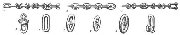
Anchor chain:
a - bow anchor chain (with anchor bracket); b - intermediate bow; c - the root of the bow; d - swivel; e is a long link; f is a large link; g - ordinary link; h - link with spacer; i - end bracket.
The anchor chain consists of separate links; several interconnected links form a bow. Separate bows are connected by connecting links. The anchor and anchor chain are connected to each other by an anchor bracket with a swivel, allowing the chain to rotate around its axis. The chain passes through a recess in the board near the cockles for the anchor, through a stopper preventing the spontaneous removal of the chain, and is wound on a chain sprocket of the anchor winch. The other end of the anchor chain is located in the chain box and is attached to the vessel by means of a cramp.
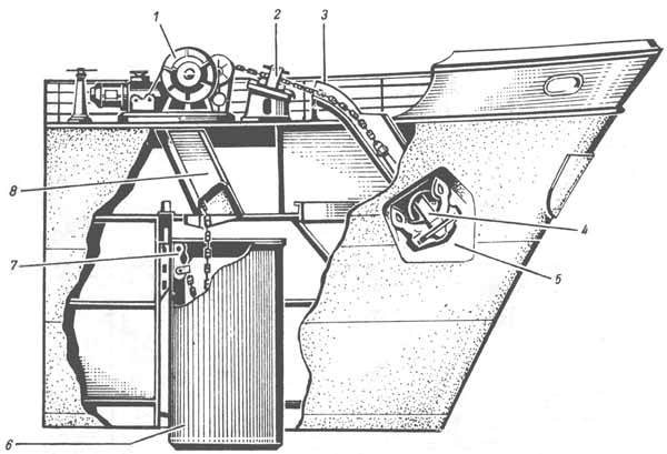
Bow anchor.
1 - anchor winch (windlass); 2 - stopper for the anchor chain; 3 - anchor lock pipe; 4 - anchor; 5 - anchor niche; 6 - chain box; 7 - device for fastening the anchor chain; 8 - chain pipe.
Anchor device is located in the bow of the vessel. The anchor winch is also installed there. The main part of the winch is a chain sprocket, which allows lifting the armature with a chain, and during winding the chain links may lie on the chain sprocket on both sides. In addition to the chain sprocket, the anchor winch also has mooring drums (turachki) for winding mooring lines. The bow anchor device includes two anchors located on the sides of the vessel. Because of the limited area for placement as an anchor winch is used in the anchor spire. It is a drum with a vertical axis of rotation towering above the deck. The drum serving as a winch has a chain sprocket at the bottom. It is driven by an electric motor mounted in a drum.
Mooring device.
The mooring device serves to moor the vessel to the berth while it is moored in the port or at the shipyard. The vessel is moored to the coast with the help of mooring lines, which are pulled from the vessel to the coast diagonally. Currently produced from various synthetic materials.
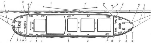
Towing and mooring device (general view).
1 - fodder longitudinal moorings; 2 - nasal longitudinal moorings; 3 - aft clamping mooring; 4 - nasal spring; 5 - fodder spring; 6 - pile bar; 7 - bollard; 8 - towing bollards; 9 - mooring spire; 10 - mooring bar with three rounds; 11 - ordinary bar; 12 - moor breech; 13 - mooring lines.
Mooring ropes are thrown onto the wharf from a vessel approaching the shore. There are braided loops at their ends, which are put on the mooring lines located on the shore of the port or shipyards. The free end of the mooring cable is laid on the side turachku anchor winch or drum anchor spire (mooring spire), and the vessel is pulled to the shore. At the end of the mooring ropes are laid around the mooring bollards and secure.
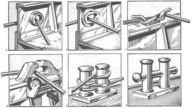
Clutches, stacks and bollards: a - mooring clew; b - moor breech; c - duck; d - ordinary bale bar with a guide roller; e - double bollard;
f - double cross bollard.
Ship shaft.
A device connecting the main ship engine with a propulsion unit. Designed to transmit torque from the main engine to the propeller, as well as to perceive the stop created by the propeller and transfer it to the ship’s hull. Shaft consists of propeller, intermediate and thrust rollers, support and thrust bearings, stern shaft, shaft swivel, brake and other devices that ensure the operation of the shaft duct. The propeller shaft is designed for fastening the propeller, and the bearings of the stern gear are its supports. The thrust shaft transmits the stop created by the propeller, thrust bearing rigidly connected to the hull. Intermediate shafts are installed between the propeller and thrust shafts to facilitate the manufacture and installation of shafting. Their bearings are thrust bearings. Shafts are usually hollow, which allows reducing their mass and provides the best conditions for heat treatment. The connection of the shafts between themselves is carried out with the help of flanges and connecting bolts or by means of removable steel cylindrical couplings. The length is 20 m.
1-DG; 2-flywheel; 3-shaft; 4-thrust bearing; 5-bulkhead gland; 6-thrust bearing; 7-propeller shaft; 8-intermediate shaft; 9 half coupling; 10 stern gear; 11-row propeller
Deadwood Device -It serves to support the propeller shaft (or intermediate) and seal the point of exit of the latter from the hull. It contains a stern tube with a stern shaft placed inside it, and inside the tube there are two bearings with water lubrication, the liners of which are formed by slats located along the axis of the shaft, characterized in that it is provided with a hull tube fixed in the hull of the vessel. said stern tube, and at least two elastic elements that are in contact with the stern tube, each of the elastic elements having an internal cavity communicated with the system working medium, and is fixed to the housing pipe, wherein the pipe mounted in the body active radial magnetic bearings with automatic regulation system working gaps which face the stern tube and the end faces of the stern tube and the housing are provided with tapered elements corresponding to each other. In places where the shaft passes through watertight bulkheads, bulkhead seals are installed.
Bulkhead seal: 1-bulkhead; 2-Fat; 3-shaft; 4-gland packing; 5-bronze ring; 6-pin bushing; 7-pressure ring; 8-building; 9 oiler.
Seawater system.
1 - Kingston
2 - Seawater Pumps
3- Refrigerator oil cooling
4 - Refrigerator fresh water cooling
5 - Refrigerator air cooling.
Ship pumps.
Pumps are the mechanisms by which liquids are transported or pumped from a room with less pressure to a room with more pressure. Depending on the principle of action, there are volumetric (piston, gear, screw), centrifugal (blade) and jet pumps. On ships, pumps are divided according to their purpose: bilge, ballast, nutritious for oil and cooling water, fire, pressure, etc. Volumetric pumps are used to periodically pump individual amounts of liquid from the suction chamber into the compression chamber. The simplest volumetric pump is a piston. The principle of operation of such a double-acting pump is shown in the figure below.
The principle of operation of a double-acting piston pump.
1 - the piston; 2-5 - valves; 6 - suction pipe; 7 - standpipe.
Another very common type of displacement pump is gear. The feed element consists of two gears placed in an airtight housing. One of the gears is driven, for example, by an electric motor. When the wheels rotate, the teeth protruding from the ring gear cause an increase in volume in the pump, due to which the liquid is sucked in by the lower inlet nozzle. Separate quantities of the incoming fluid are successively accumulated in the intermediate space between the gear wheels and are fed between the pump casing and the wheels to their outer side. Finally, the fluid enters the compression chamber. Due to the consistent entry of the wheels into the ring gear, the fluid is squeezed into the discharge port. Gear pumps are used on vessels to pump out viscous liquids with good lubricating properties, such as oil, fuel, etc.
Screw pumps also belong to the group of volumetric pumps. Liquid from the intake manifold enters the intermediate spaces between the screws, which are also called cameras and are located between the lead screw connected directly to the engine and the follower. After turning the screws at a certain angle, the liquid in the chamber is locked; then it goes up along the screws and from there it is injected into the pressure pipeline. If the pressure in the compression chamber is too high, the safety valve opens and the fluid flows back into the inlet chamber.
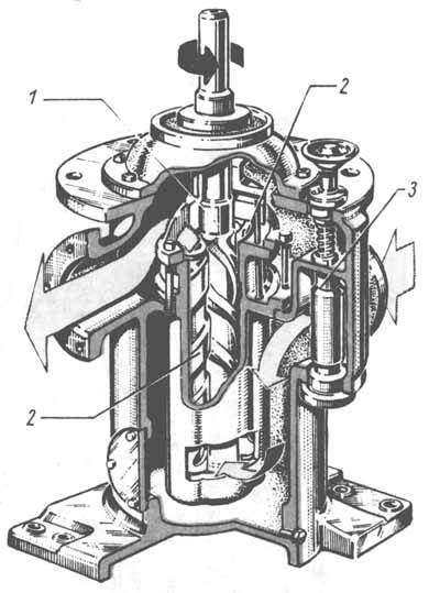
The principle of the screw pump.
1 - drive shaft; 2 - driven screws; 3 - safety overflow valve.
The principle of operation of the centrifugal pump is shown in the figure below. A characteristic feature of these pumps is a continuous flow of fluid. The working body of the pump, the rotor with blades, is mounted on a rotating shaft of the pump, which is most often connected directly to the drive motor. The blades of the rotating rotor transfer the energy of the engine fluid flowing through the pump, creating pressure, under the influence of which the fluid flows from the entrance to the exit. Centrifugal pumps are commonly used in ship power plants. They have a different design depending on the power. Thus, the power of injection pumps for tankers reaches several thousand tons of fluid per hour. If the pumped liquid (for example, water in fire pumps or feed pumps of steam generators) requires a higher pressure, use multistage pumps. The principle of their operation is that water, which has reached a certain pressure and leaves the first stage, flows to the next-stage suction nozzle, where the pressure rises again.
Air compressor.
Compressors are machines by which gases are compressed from a low inlet pressure to a high outlet pressure. The ratio of these two pressures is the compression ratio. The simplest and most often used on ships compressor is a piston. By the principle of action it is identical to the diesel engine discussed above. As the gas temperature rises during the compression process, a compression ratio in the cylinder of the compressor can only be obtained within six to eight. A further increase in the degree of compression leads to an increase in temperature, which has a detrimental effect on the compressor. If it is necessary to obtain a higher pressure (for example, to start the main engine, an air pressure of 2.9 MPa is required), use multistage compressors. Air of atmospheric pressure (0.59 MPa) is sucked into a high-pressure cylinder with a smaller working volume than in a low-pressure cylinder, since the amount of air decreases due to compression in the low-pressure cylinder and cooling in the cooler. In the high pressure cylinder, you can again increase the air pressure six times. The final air pressure will then be 3.5 MPa.
Separator of fuel and oil.
Separators installed on ships are designed to clean fuel and oil from mechanical impurities and water. The separation of mechanical impurities and water, as heavier particles, occurs in centrifugal separators under the action of centrifugal forces arising from the rotating movement of fuel or oil. On sea vessels, centrifugal separators of disc (disc) type are self-cleaning or with manual cleaning installed. The separation of dirt and mechanical impurities from the fuel is called clarification (clarification), the separation of water - purification (purification).
Watered and contaminated fuels are cleaned using a combined purification. For this purpose, two separators are installed on ships, one of which works in the mode of clarification, the other in the mode of purification. Separation of oil and separators for it are no different from the fuel separators and in the presence of a connecting system can be interchanged. On seagoing vessels, disk separators of the type NCS, Laval, Titan, Westfalia and other foreign firms are installed.
The assembly of drums for clarification and the assembly for purification differ from each other.
a - for clarification, b - for purification;
1 - a plate without a hole, 2 - mud space, 3 - a plate with holes.
The rotary separator drum, assembled as a clarifier (Fig. A), receives fuel through the central channel in the lower part of the drum, is thrown to the walls, passes through the gaps between the plates and is discharged through the ventilation openings (shown in the figure with arrows). Mechanical impurities and dirt are deposited on the walls of the drum and on the surfaces of the plates under the action of centrifugal forces. The sediment from the walls of the drum and from the plates is removed manually when disassembling the separator.
The method of clarification is used when there is a significant amount of mechanical impurities and a small amount of water in the fuel. Water, leans back together with mechanical impurities, fills the entire mud space 2 and forms a hydraulic valve, which will block the flow of fuel between the plate gaps. Fuel entering the drum in a continuous stream will begin to pour out of the overflow pipe. In this case, the separator is stopped and the drum is cleaned. During clarification, the separator is started with a dry drum, and when it develops the necessary revs (8-10 thousand rpm), it is gradually filled with fuel.
For the separation of flooded (up to 3% and more water) fuel separator drum is collected as purifier (fig. B). To do this, install the bottom plate 3 with holes. When the separator is working according to the purification method, the drum is filled with warm water, the temperature of which should be the same as the temperature of the separated fuel. Water forms a water seal, and the fuel passes through the holes in the plates. Water and mechanical impurities are separated from the fuel in between the plate gaps and sent to the walls of the drum. The separated water is continuously removed from the drum (shown in the figure with arrows). Self-cleaning separators differ from non-self-cleaning drum designs, the cleaning of which occurs without stopping the separator.
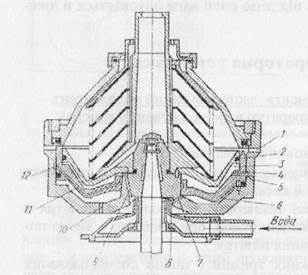
1 - discharge opening; 2 - shutter piston; 3,6 - water cavities;
4,7,9,10 - holes; 5 - drain valve; 8 - camera; 11 - channel; 12 - annular groove.
The figure shows the device drum self-cleaning separator SCS-3.
Discharge openings 1 are cut on the walls of the drum, through which dirt is separated, separated from the fuel. The discharge openings are closed by a closing piston 2. The right-hand part of the figure corresponds to the position of the locking piston when the drum is cleaned, and the left part is when the fuel is separated. At the time of the start of the separator discharge openings are open and the piston is in the lower position. The piston movement is controlled by a special hydraulic system, the working fluid in which there is water. When the drum picks up the required number of revolutions, water is fed into chamber 8, from where it goes through holes 7 and 9, respectively, into cavities 6 and 3. From cavity 6, water is drained out into opening 10. And from cavity 3, through hole 4, channel 11 in the body of the piston to the annular groove 12 in the wall of the drum and the channel 5. The water supply stops after filling the system of cavities and channels. From cavity 6, part of the water flows out between the hole 10 and the drum core, while from cavity 3 water is completely drained. As a result of the action of centrifugal forces, the water remaining in cavity 6 creates pressure on the locking piston, which rises and blocks the discharge openings. After that, the fuel is supplied to the separator and the cleaning of the fuel takes place as described above.
To clean the drum, water is again supplied to chamber 8, from which water starts to flow into the cavities 6 and 3 through the hole 7 and eight holes 9. In the cavity 3, water accumulates much faster, as it is fed through eight holes. Water accumulated in cavity 3 lowers the piston. To clean the separator, the fuel supply to the drum is stopped and heated water is supplied in a large amount. The accumulated dirt under the action of centrifugal forces is ejected from the drum through the discharge openings. After stopping the separator, water from cavity 6 flows and the piston is lowered to the lower position by gravity.
Bilge water separator.
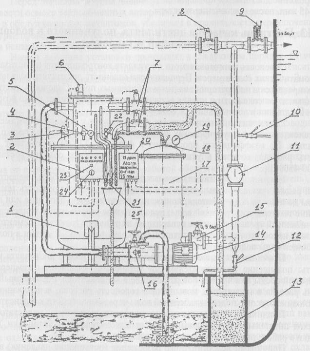
1-body separator; 2-control panel; 3-pins sensor monitoring the content of oil products; 4-safety valve; 5-gauge; 6-pin sensor control the content of petroleum products; 7-pneumatic piston discharge valves of petroleum products in the collection tank; 8-electro-pneumatic valve for returning bilge water with an increase in oil content in it above 15 ml / l; 9-spring-loaded valve drain water overboard: 10-tap water supply for flushing; 11-alarm alarm sensor with an increase in oil content in the discharge water above 15 ml / l; 12-tap water drain; 13-pack oil tank; 14-screw pump;
15 non-return valve clean water outlet; 16 solenoid valve for protection of the screw pump; 17-filter housing; 18-tap removal of oil and air;
19-gauge; 20-cabinet alarm; 21-taps of oil from the separator; 22-tap to remove air from the separator; 23- control button of the automation system; 24-main switch automation system; 25-way valve between separator and filter.
Operation of the RWO separator. Before commissioning the separator unit "KM" it is necessary to check the supply of compressed air and power supply to the automation system. In the absence of power supply automation systems, both piston valves 7 of the outlet of petroleum products are in the closed position.
The installation should be entered in the sequence indicated below.
1. Open the valves on the compressed air pipeline, the pressure gauge should show a pressure of 0.4 to 0.5 MPa.
2. Turn on the main switch of the automation system 24, thus the green “Work” warning lamp and the red oil-in-tank warning light should come on.
3. Fully open the spring-loaded drain valve 9 on the overflow pipe overboard and the stop valve 25 between the separator and the filter.
4. Switch the group of valves in front of the separator pump so that clean seawater is drawn in to rinse the separator.
5. Start the separator pump 14.
6. Fill the separator installation with clean seawater until water appears through the air release valve 18. Air is automatically removed from the primary and secondary separator chambers through the piston valves 7 to the collection tank 13. After the separator is completely filled with water, the “Oil into the collection tank "and the green indicator lamp" Water overboard "lights up. With a view of safety and exclusion of the ingress of oil products overboard, check the separator filling and the presence of oil products in water by opening the drain valves 21.
7. Perform a test of the functioning of the automation system, for which it is necessary to press the control button 23 and hold it for 10 seconds. After that, the oil-in-tank control lamp should light up and the piston valves will open.
8. With the pump running, throttle the spring-loaded drain valve 15 until pressure gauges 5 and 19 show a pressure of about 0.1 MPa.
Switch the valve group on the intake manifold so that the HB is received from the required well in the engine room.
After this, the “RWO” installation is ready for operation.
During the operation of the separator installation it is necessary to maintain the following parameters:
The temperature of the heating in the separator HB - 60 ° C;
Pressure in the filter housing - 0.1 MPa;
Pressure in the separator - 0.15 ... 0.2 MPa;
Compressed air pressure - 0.4 .. .0.6 MPa;
Periodically carry out manual oil removal from the separator and filter caps;
Periodically monitor the operation of the automation system by pressing the control button on the control panel of the control device.
Plan
Section 1. Organization of service on ships of maritime transport.
1.1 Basic provisions of the statute of service on transport ships.
1.2 Organization of service on the vessel.
The basis of the organization of the ship service are:
Institutional schedules;
Watch service;
Technical service;
Alarm schedule;
Schedule of labor protection.
Crew members should know and carry out:
Their duties, to participate in the solution of the production tasks assigned to the court;
Know your specialty and constantly improve it;
Know and strictly observe the PTB, skillfully fight for the survivability of the vessel, be able to use individual and collective rescue equipment;
Provide safe operation ship and prevent pollution.
(see question 76)
What we will do with the resulting material:
If this material turned out to be useful for you, you can save it to your page on social networks:
| Tweet |
All topics in this section:
Emergency property of the vessel. The way to announce alarms on ships.
Patches are classified into soft, rigid, pneumatic. Soft plasters include: a band-mail patch (Baranov patch), lightweight
Towing device of the vessel. Elements of the towing device. Rules of TB in the technical operation of the towing device
Towing device - is a set of products and mechanisms that provide the vessel with the ability to tow other vessels or to be towed.
Types of briefings on labor protection. Frequency of briefings.
Primary briefing and on-the-job training at the workplace of newly recruited, transferred from one vessel to another (even if these vessels are of the same type), learners who arrived at work
Types hatch covers. Rules of technical operation and safety measures when working with them and in cargo holds.
Cargo hatches, simple hatch covers, mechanized hatch covers. It is prohibited to open hatch covers until the space around the hatch is appropriate.
Arming heavy cargo booms and methods of operation.
A heavy boom is made much stronger than an ordinary one and is located in a DP vessel. To reduce the stresses in the mast, the boom spurs do not rest on the mast itself, but on a special foundation,
Horizontal sectors of the visibility of navigation lights
Rule 23 and Annex II of the COLR. The vessel must carry: a masthead light in front, a masthead light behind and above the front masthead light (for vessels more than 50m long). Side lights and stern light
HORIZONTAL LOCATION OF LIGHTS AND DISTANCE BETWEEN THEM
If two top lights are prescribed for a motor-driven vessel, the horizontal distance between them should be at least half the length of the vessel, but it is not necessary
Cargo device and its composition. Purpose of the device. Safety when working with a cargo device.
Due to the ease of operation on ships, cargo devices with arrows are common; modern ships are more often equipped with electric and hydraulic cranes. Stationary shipboard carrying capacity
To define what is and for what purposes the products, devices, details of the device of the vessel and other terms used on the vessel are used.
Steering gear - designed to provide controllability of the vessel. Consists of a working body and steering wheel, a rudder - for its turning, steering gear, steering gear
Documents required for the position of a sailor.
1. Seaman's passport 2. International sailor certificate 3. First aid certificate. 4. Lifeboat and raft specialist certificate.
Pollution of the sea. Convention. Marine Pollutants. Signs of pollutants, marking.
SEA POLLUTION is an offense of an international nature committed on the high seas; consequence of shipping, dumping and dumping of industrial and household waste, mining
Marking and labeling.
1. Cargo packages containing a harmful substance are marked with reliable durable markings with the correct technical name (you cannot use some commercial names) and they must be reliable
Reserve buoyancy of the vessel and cargo mark. Where is the cargo mark on the ship
FLUORY RESERVE STOCK: the volume of the water-impermeable surface part of the vessel, located from the load (constructive) waterline to the upper continuous
Knowledge of the main work performed by the deck crew and the tools used in the deck work.
The 1st class sailor is responsible to the boatswain for: 1) General maintenance of the vessel as directed by the boatswain. 2) Participation in mooring and anchor operations of the vessel. 3) Maintaining your own
Measurement of distances at sea. Basic units and speeds adopted in navigation. Instruments for measuring speed and distance traveled at sea.
The distance to landmarks at sea can be measured using a radar, range finder or sextant. The most simple and accurate measurement of the distance is performed by radar. Range finders,
Life jackets.
Personal equipment includes: 1) protective clothing made of a material capable of protecting the skin from heat emitted during a fire, burns and scalding; the outer surface should be water
What activities are carried out on the ship in the port to ensure navigation in stormy conditions.
Preparation of the ship for sailing in the storm begins when moored in the port. The correctness of loading is to provide the ship with local and general strength, sufficient stability, delivery of cargo
What works need to be done to maintain the hull in good condition.
Properly organized care of the hull of the vessel and its premises offers, first of all, the prevention of metal corrosion and wooden rotting, the main method of protection of which is
ISPS Code. Security levels
ISPS - Code for the Security of Ships and Port Facilities adopted on 12.12.2002. Security level 1 (Securitylevel 1) - means the level at which the minimum correspondences should be constantly maintained
Code of merchant shipping of Ukraine, purpose of the code.
The Merchant Shipping Code of Ukraine regulates the attitude that arises with merchant shipping. Under the merchant shipping in this code means activities related to the use of
Constructive and organizational measures for the SPS.
The main document regulating the prevention of marine pollution (PZM) from ships is the International Convention for the Prevention of Pollution from Ships MARPOL 73/78. Constructive measures
Marking lifeboats and rafts.
Information about the capacity of the boat, as well as its main dimensions, are applied to its sides in the nose with indelible paint; the name of the vessel, port of registry (letters of the Latin alphabet) and court
International conventions in the field of maritime shipping and their role.
SOLAS - 74– International Convention for the Safety of Life at Sea. ISM Code - International Security Management Code. PDNV -
Marine Distress Signals
· Puffs of orange smoke · Open flames on the ship · Red light flare · Flag signal NC (NC)
Distress lights
· Signal mirror · Signal fire (3 fires at a distance of at least 50 meters from each other, so that when viewed from above they form a triangle or a straight line) · signal SO
International Code of Signals. Rules of negotiation on the MCC.
The international code of signals (TheInternationalCodeofSignals; INTERCO) is intended for communication in various ways and means in order to ensure the safety of navigation and protection
Security measures and paint work
Before starting work on the preparation and painting of surfaces (depending on the place of their execution), the following activities should be envisaged: - checking the reliability and readiness of forests and the imp
Precautions when transporting by sea.
The ship administration is fully responsible for the correctness of receiving, packing separation, unloading and delivery, as well as for the compliance of documents and the condition of the cargo. During the flight
Flammable liquids.
Flammable solids. Substances capable of spontaneous combustion. Oxidized substances. Must be placed in cool places away from everything
Precautions for the transport of dangerous goods.
Members of crews of ships having a work experience in the specialty of at least 1 year, who have undergone training and an annual knowledge test and briefing at the workplace on b) are allowed to work with dangerous goods
Precautions when conducting fumigation, degassing of the vessel
Transit fumigation in the vessel - disinfection of cargo in the ship’s holds without taking it out of service, takes place during the voyage and ranges from 5 days or more depending on the depths
Methods of dealing with water. The procedure for filling the patch.
To eliminate the water flow of the hull and various damage, the vessels are supplied with emergency equipment and materials: - all waterproof doors are dragged down; - pressurized
Fire fighting methods on ships. Ways and means of extinguishing a fire.
The crew’s fight against fire on the ship is headed by the ship’s captain and should be aimed at: · detecting and identifying the place, size, nature of the fire; · Establishing availability and
Boat knot
It is used when towing boats and during their stay under a shot at the side of the ship only when there are people in them. At first the running end of the falin is passed into the bow boat.
A set of ship hull. Recruitment systems. Appointment and device of a double bottom. The main transverse and longitudinal connection.
The hull is a shell consisting of horizontal and vertical plates, supported by beams. The combination of the plate with its reinforcing beams is called overlap
The appointment of a gyrocompass, magnetic compass. The main parts of the magnetic compass. Types of magnetic compasses. Comparison of compasses.
A compass is a navigation device designed to determine the ship’s heading and directions to various coastal or floating objects in the navigator’s field of vision. Compass is used
Unsinkability of the vessel. Measures to ensure the unsinkability of the vessel. Marking waterproof bulkheads.
Floodability - the ability of a ship to stay afloat and not to tip over if its hull is damaged and one or several compartments are flooded. Fight for non-flooding
The equipment of places of carrying out cargo works. Signal Officer Responsibilities
Dockers-machine operators (DM) who have been trained, have worked in the port for at least 1 year, qualified as a signalman and who know the signal system
General rules for the production of paint work on the ship. Preparation of surfaces for painting.
Painting work on the vessel (including engine rooms) is headed by a boatswain. The senior sailor (carpenter) is responsible for the preparation of the required tools, materials, protective
Responsibilities of the sailor of the watch on the ship. The form of the report looking at the detected object.
The watch sailor reports directly to the watch officer assistant captain. In the course of the vessel, watch sailors perform mainly two main functions: they stand on the steering wheel and carry on a visual-auditory observation.
Responsibilities of the sailor of the watch while stationed in the port
While the ship is moored at the berth in the port, the watchman is constantly at the gangway, who monitors the vessel’s visit, preventing unauthorized persons from entering the ship
Supervisory responsibilities. Boat propulsion Ship agility
A sailor of class 1 submits to the senior sailor and, if necessary, replaces him. Sailor class 1 must: - know general information by navigation, coloring and beyond
Responsibilities of crew members upon detection of a fire or water-tightness on a ship.
In the event of an emergency, the captain exercises overall control over the actions of the crew in the aftermath of the emergency and the struggle for the survivability of the vessel. In case of imminent death the court
Mandatory minimum requirements for the rank and file persons carrying the navigation chassis watch.
Rule II / 6. Mandatory minimum requirements for the rank and file persons carrying the navigation chassis watch. 1. Minimum requirements for rank and file marine animals
Regulation 29. PILOTS VESSELS
a. The vessel, when performing pilotage duties, shall exhibit: i. on the top of the mast or close to it - two all-round lights located in a vertical line; the top of these lights is long
Rule 7 - Risk of collision
Rule 7 - Risk of collision a. Every ship should be
Art. the mechanic is in charge of the technical operation of the entire mechanical and electromechanical parts of the vessel.
77. Definition of IC: PI, KU. Commands given to the helmsman when turning and changing course. How to lead a ship on a course on a magnetic compass? Emergency steering.
Definition and terms relating to keeping the watch. Compliance with the requirements of the ISPS Code.
Section 2. Definition Contains 11 definitions, of which three (such as 1.Cjgvention, 2.Regulation, 3. Chapter) are well known, and the remaining 8 are given below: 4. ShipSec
Labor organization in the conduct of general shipwork.
Preparation for the work should include the organization of a safe and convenient workplace, the correct placement of workers, the provision of working specials. clothing and protective equipment.
The main actions related to the protection of the environment when entering the territorial waters of states.
1. Before the vessel enters the water, stop any operations of oil-containing mixtures and other harmful liquid substances. 2. All locking devices through which these substances are discharged are
Ship stability Stability measures. Deadweight ship.
Stability is the ability of the ship, rejected from the position, equilibrium, to return to it after the disappearance of the cause that caused the deviation. Deadweight - the difference between the displacement
The first pre-medical assistance to victims of accidents.
1. Terminate the effect of hazardous factors on the injured person (release from the action of the electric current, take out the contaminated area, extinguish clothing that is burned out of the water, etc.) 2. Inject the injured
Floating equipment navigation equipment. Hazard guard systems.
A floating beacon is a vessel equipped with lighthouse light equipment, radio engineering, and sound-signal devices and designed to determine the position of ships at sea. Buoys - applied
Preparatory work for the reception and delivery of the pilot.
1. Establish communication with the pilot station or with the pilot ship. 2. To clarify the time of approach to the point of reception (return) of the pilot. 3. Prepare a pilot ramp (gangway) to check the wasps
Preparation of cargo premises (tanks) to receive cargo.
The main activities for preparing cargo space for receiving cargo are: All cargo space should be fully prepared to receive cargo (swept up, washed, if necessary
Preparation and launching of lifeboats and rafts. Landing in boats and launching them into the water.
Before launching the boat into the water, a number of actions must be performed: 1. Regardless of the method of launching the boat, additional equipment and supplies necessary for
The procedure for determining directions on the surface of the Earth. Systems of division of the horizon into degrees and points
An observer on the surface of the globe can determine the direction of a certain line using a plumb line. Sheer line on the surface of the globe will give direction to the zenith of the observer
The order of abandonment of the vessel in the absence of rescue equipment at the side of the vessel.
Jump into the water in a lifejacket: - put on a vest, firmly press it with your hands; - to inspect the landing place, take a deep breath, push the legs forward from the side, facing the sea;
Rules for the use of signal pyrotechnic means. Marking pyrotechnic signal means.
Pyrotechnic alarm devices are included in the supply of lifeboats and life rafts and are used to give distress signals and attract attention. These include:
Safety regulations for the production of freight operations, mooring operations.
On each lifting device are indicated: - register number; - permitted load capacity; - the term of the next test is FORBIDDEN to work as a cargo pendant
Causes of fires on ships. Portable and stationary fire extinguishing equipment.
The main causes of fires on the vessel. Treat: - indisputable or careless handling of open fire, heating devices, careless smoking; - fault
Fire mode on the vessel. Sentinel service.
The crew of the vessel must strictly observe the fire protection regime and take all measures to ensure the explosion and fire safety of the vessel in any conditions of its operation. When parking sous
Mast and rigging of the vessel. Their purpose
A mast is a structure made of metal pipes or wooden blocks that are installed in the center plane of the vessel and are rigidly fastened to its body. The mast includes the masts and their
Schedule for alarms. Responsibilities for anxiety. Types of ship alarm.
The main organization of the struggle for the survival of the vessel is the Alarm Schedule. It defines the duties of the crew members in case of an accident and the place of their collection for the alarms. There are typical odds
Steering gear vessel. The composition of the steering device. Types of steering wheels, steering gears.
The steering device provides controllability of the vessel, i.e. keeps the vessel on course or change its direction of movement regardless of the influence of wind, waves or currents. Composed:
Sanitary regulations and ship hygiene.
Sanitary rules contain requirements for water supply, heating, ventilation, household and waste water systems. Sanitary regulations regulate the standards of illumination of working places;
Separation equipment for bilge water treatment. Waste incineration equipment.
Each vessel with a capacity of 400 rt and more, oil tanker with a capacity of 150 rt and more should have on board: - filtering equipment that provides purification of oily water to
The system of internal and external communication and alarm systems on ships.
Internal communications and alarms are designed to ensure control of the vessel and reliable communication of the command bridge with all posts and services. These funds include: - ships
Cardinal system
· Northern buoy: · Coloring: black at the top, yellow at the top Top figures: both cones tops upwards Fire: flashing without pauses, by
Special purpose signs
Designed to refer to special areas or objects shown on maps or described in other navigation documents, such as signs, fencing off landfill areas, underwater cables
Rescue and duty boats and their types and requirements for them.
A lifeboat is a lifeboat capable of preserving the lives of people in distress since they left the ship. Closed type boats and partial closed type boats
Means of internal and external communication and alarm systems on ships.
Internal communications and alarms are designed to ensure control of the vessel and reliable communication of the command bridge with all posts and services; - ship telephone communication; - ships
Means and methods of visual signaling.
1.Signal - distinctive lights (running lights) - top lights; - side lights; - stern (gakobortny) fire; - bunker fire; - anchor lights;
Means of navigation equipment, their types of location, purpose, principle of action.
Navigation equipment of the ship consists of a set of navigation instruments that provide the course laying, determining the geographical coordinates of its location. These devices should provide
Ship fire systems, fire extinguisher brands and their use.
Fire extinguishing system: Water extinguishing - consists of fire pumps, fire horn, hoses, barrels. It is in constant readiness. Sprinkler system - designed for av
Ship systems and their purpose. What is a ship fire extinguishing plan?
Ship systems are a combination of specialized pipelines with mechanisms, devices, instruments and installations. They are designed to move fluids, air or gases into
Fire extinguishing plan
Firefighting on ships is carried out in accordance with operational tactical maps and fire extinguishing plans. The fire extinguishing plan is a scheme on which plans are plotted in
Ship anchors, their types, requirements for them. The rules of TB in the production of work anchor device.
Hall anchor has a small number of parts and a large holding force. Being buried in the ground with both paws, the anchor does not pose a danger to other vessels in shallow water and excludes the possibility of
Safety in the performance of general shipwork. Industrial sanitation on ships.
The crew of all specialties must be aware of and follow the general requirements of the safety device when operating the vessel. For the safe execution of general shipwork, team members are provided with workwear and
Requirements for the steering device. Checking the steering device before entering the flight. Standard length of intermediate bows of the anchor chain.
In preparing the ship for work, all details of the steering device are carefully inspected, lubricated if necessary. Axiometers are checked. Check the stopper. All defects found
Cables and rigging, cable maintenance.
Cables (ropes) are products made of steel wires or twisted from plant and artificial fibers. Vegetable cables are made from vegetable fiber (hemp, mani
Conditions for dumping ballast and garbage from ships.
“Garbage” means all types of food, household and operational waste that forms during the normal operation of the vessel and is subject to permanent or periodic disposal.
Device hull ships, the purpose and the main elements of a set of hull.
Apply three systems set: transverse, longitudinal, combined. In the transverse system of the set, the main beams go across the vessel (flora, frames, beams) In the longitudinal system
Ship bulkheads
To ensure floatability, the vessel is usually divided by special bulkheads into compartments, which prevents it from being completely flooded due to local hull damage. Bulkhead reinforce the building
Exercises on the transition to emergency steering. The procedure for the transition to emergency steering.
The transition from the main steering gear to the spare should be done quickly: two people should do this work in no more than 2 minutes. To acquire the necessary practical experience of the ship
Anchor device. Preparation for release and anchor sampling.
Anchor device provides a secure parking of the vessel at sea or on the roadstead. When approaching the anchorage, they say the entire anchor device and first of all the windlass. Windlass
Anchor isostrostvo. Appointment and composition. TB in the return and selection of the anchor.
Anchor device - provides a secure parking of the vessel in a given area of the sea. The main elements of the anchor: anchors, anchor chains, anchor mechanisms, klyuzy, stoppers. Anchor
Federal State Educational Institution
Higher education
"KERCH STATE MARITIME
UNIVERSITY OF TECHNOLOGY"
(FSBEI HE "KGMTU")
Maritime Faculty
Department "Navigation"
I APPROVE
Head Department of Navigation
G.I.Pazynich
“____” ________________ 2015
ABSTRACT LECTURES OF EDUCATIONAL DISCIPLINE
"THE ORGANIZATION OF THE SERVICE ON FISHING SHIPS"
Level of the main educational program - specialty
Specialty - 05/26/05 “Navigation”
Profile - “Commercial navigation”
The status of the discipline is variable.
Lead Lecturer
KDP Rodchenkov A.V. - Senior Lecturer of the "Navigation"
Considered at the meeting of the department "Navigation" FSBI of HE "KGMTU"
Minutes No. ____ of ____________ 2015 Head of the Department _____________ G.I. Pazynich
Kerch 2015
Kerch State Marine Technological University
S U D E F G H A N I E
INTRODUCTION.
Shipowner. CAPTAIN SHIP. CREW SHIP.
1.1 Shipowner. Obligations of the shipowner according to the SMS.
1.2 The main tasks and crew. Captain of the ship. Rights and obligations under the Charter of the service on the vessels of the fishing fleet of the Russian Federation, KTM. Ship schedules and supervisors.
ORGANIZATION OF SERVICE ON SHIPS OF FISHING INDUSTRY FLEET OF THE RUSSIAN FEDERATION.
2.1 Watchkeeping service. The organization of the watch. Reception, delivery of the watch. Watch for parking
ship in port, anchored, repaired.
2.2 Principles of carrying a navigational watch at sea on the move, in the field with
with fishing gear.
2.3 General court service, radio engineering, ship mechanical, medical and sanitary,
fish catch service, fish processing service, ship training, and scientific and technical services.
MANUFACTURING ON MARINE, FISHING SHIPS.
3.1 Record keeping on sea, fishing vessels. Registration of arrival / departure of the vessel. IMO document forms for vessel arrival / departure.
3.2 Ship documents issued by the shipowner.
3.3 Ship documents issued by the Port Authority (harbor master).
3.4 Ship documents issued by RMRS.
3.5 Ship's documents issued by the fire inspectorate and the DIS of the port.
3.6 Status of the ship's log. Rules for filling (maintaining) the logbook.
USED BOOKS.
Introduction
The efficiency of operation of vessels is inextricably linked with the unquestioning implementation of the provisions and requirements of international and national documents to ensure the safety of navigation and fishing.
Good learning by cadets of the program "Organization of service on fishing vessels" is a necessary condition for the formation of a marine specialist.
The purpose and objectives of the study of the discipline are that the cadet after the assimilation of educational material could:
To know and be able to apply in practice the requirements for maintaining the vessel, its devices and supplies, ensuring safe navigation,
Know and be able to apply in practice international and national requirements for ensuring the buoyancy and unsinkability of the vessel,
Know the problems in ensuring trouble-free swimming and the impact on the accident rate of the human factor,
Know the practical measures to ensure the safety of the vessel in the fishing industry,
Know the methods of preventing sea pollution from ships and environmental protection and be able to carry out measures to prevent pollution,
Know the principles of organization and ways to save people at sea.
The ultimate goal is to train cadets who are able to navigate in a normal and extreme situation (situation) and who are capable of ensuring the safety of navigation and fishing.
1. SHIPOWNER. CAPTAIN SHIP. CREW SHIP.
Shipowner. RESPONSIBILITIES OF THE SHIPPERSON ACCORDING TO THE SUB.
Lecture number 1
Shipowner Obligations of the shipowner according to the SMS.
1. The concept of the shipowner.
2. Obligations of the shipowner according to the SMS.
The service on ships of the navy is organized in accordance with national regulatory documents: KTM of the Russian Federation in 1999, the Charter of service on the vessels of the fishing fleet of the Russian Federation, RShS-89 and the international conventions for STCW 78, ISMC, and the SMS of the shipowner, ISPS.
The shipowner organizes and prepares the ship for safe operation. It monitors the availability and duration of ship's documents on the vessel, issued by the authorized supervisory authorities and certifying the ship’s compliance with the requirements of national and international safety rules and standards and their suitability for navigation, in particular, it is its responsibility to ensure the ship, all the shipboard services necessary documentation and manuals, operating instructions, all navigational aids (navigation charts, ship flats, navigation literature, global maritime aids, etc.) for a complete to operate the vessel, its hull, main engine, ship machinery for ship services, and also provide the ship crew with food for a certain period, spare parts, working clothes, medicines and medical equipment, personal hygiene of the crew and ship services before the vessel’s departure, the shipowner must provide it with the necessary amount of fuel and oils, necessary supply supplies and equipment, fish processing facilities, and e means of self-repair by the crew of the ship itself, its hull, superstructures, mechanisms that may be damaged during navigation in stormy conditions, under force majeure circumstances, mooring operations in the open sea with other ships, etc. When a vessel is on a flight, in the field, constantly monitor (daily) the vessel’s location, its fishing activity, weather conditions in the area where the vessel is located, and (first of all) the condition of the ship’s crew (illness, injury, medical care, delivery of patients to the shore, urgency provision of coastal medical care). It organizes the timely presentation of the vessel to the supervisory authorities for the renewal or renewal of ship's documents in accordance with the established regulatory deadlines for their action.
The owner of the ship develops shipboard staffing schedules and takes care of completing the vessel with a crew with qualified Conventional working documents, checks for documents confirming that a member of the crew has passed a medical commission to work at sea.
The shipowner must properly issue the employee a job (contract, employment contract) and respect the seafarer's hard work, taking care of the timely payment of his salary to him (his family).
The shipowner announces the company's security management policy, prepares and presents the ship for compliance of the SMS to the supervisory authorities.
SELF-CONTROL QUESTIONS
1. On the basis of what documents is the service organized on ships?
2. Obligations of the shipowner?
THE MAIN TASKS AND COMPOSITION OF A FISHING SHIP CREW. CAPTAIN SHIP. RIGHTS AND RESPONSIBILITIES ACCORDING TO THE CHARTER OF THE SERVICE ON SHIPS OF THE FISHING FISH OF THE RUSSIAN FEDERATION, KTM. SHIP SCHEDULES AND INSTITUTIONS.
Lecture number 2
The main tasks and composition of the ship's crew. Captain, rights and obligations according to the Charter of the service on the vessels of the fishing fleet of the Russian Federation, ISM, KTM, PDNV-78.
The main issues addressed in the lecture:
1. The main tasks and crew.
2. Rights and obligations of the captain.
3. The responsibility of the captain.
The main tasks of the ship's crew are to ensure the safe operation of the ship, to prevent damage to people on the ship, cargo, property, ship and the environment. Protection against identified risks and constant readiness for action in emergency situations. The crew consists of the captain, other officers, and the crew. The commanding staff, besides the captain, includes assistants to the captain, mechanics, electrical mechanics, mechanical engineers, masters of fish extraction, masters of fish processing, radio specialists and doctors. The ship crew consists of non-command personnel. The ship's crew is divided into service. The senior mate of the captain, the watch mates of the captain, and the sailors belong to the general court service. The senior mechanic, the second mechanic, mechanics, electricians, engine mechanics and electricians belong to the ship-mechanical service. Other crew members are divided into services depending on the main duties performed by them.
Captain - the person commanding the vessel. He is the highest official and trustee of the shipowner on the ship, is fully responsible for the safe operation of the ship, preventing damage to people on the ship, cargo, property and the environment, protection from identified risks and constant preparedness for emergency situations.
The captain controls the vessel on the basis of unity of command. All instructions, orders and orders relating to the activities of the vessel are transferred only to the captain responsible for their execution. All crew members are assigned to the vessel with the consent of the captain. He has the right not to take on the vessel any person, including that designated by the shipowner. The captain issues orders and gives orders that are subject to unquestioning execution by all on board.
A lot depends on the captain, on his actions when the vessel conducts the fishing activity. Proper operation of the vessel, its field mechanisms, captain fishing experience, command of the vessel’s crew, human factor, ability to communicate with
people to help solve difficult working problems, difficult everyday situations, and sometimes family issues within the competence and guided by regulatory and legal documents - the pledge, as a rule, the excellent work of the ship’s crew during the voyage, fishing activity of the ship in the fish and seafood industry.
Lecture number 3
Command staff and ship crew. Ship services. Ship timetables. Ship management.
The main issues addressed in the lecture:
1. Command Staff
2. Ship team.
3. Ship services.
4. Ship timetables.
5. Schedules for supervisors.
The senior assistant to the captain submits to the captain, is his first deputy, heads the general judicial service and supervises the work of the assistant captains. He must be ready at any time to replace the captain and take command of the vessel. Considering the captain’s sole responsibility for the safety of the ship and that the senior mate of the captain should be ready to take on this responsibility at any time, his competence should correspond to the competence and professionalism of the captain in relation to this responsibility at the management level.
All crew and its orders on the organization of service and daily routine on the vessel, emergency and emergency work, alarms, preparation of the vessel for arrival and departure are obligatory for all crew members.
The senior mechanic reports to the captain, is his deputy for the technical operation of the vessel. He heads the ship-mechanic service and manages the work of mechanics, electricians, ref. Mechanics, etc. He must possess competence and professionalism in relation to the implementation of basic functions at the management level - ship mechanical installations, electrical equipment, ref.equipment, etc. Electronic equipment and control systems and maintenance and repair, know national and international rules and regulations on their structural, environmental and technical and operational safety of ships.
The second mechanic submits to the senior mechanic and is his first deputy. He must be ready at any time to replace the senior mechanic and assume responsibility for the technical operation, management of the machine team. Given this, his competence and professionalism must correspond to the competence and professionalism of the senior mechanic in relation to this responsibility at the management level.
Watch assistants captain obey the senior assistant captain, and during the watch, the captain. They must possess competence and professionalism in relation to their performance at the operational level of the main functions — navigation, fishing, loading, cargo handling, and ship operations. Watch officers of the captain carry the running and parking watches and are responsible for the safety of the vessel during their watch. They should manage all types of deck works, preparing the crew for the struggle for the survivability of the vessel.
Watch mechanics are subordinate to the senior mechanic and watch officer assistant captain. They should possess competence and professionalism in relation to the basic functions performed by them at the operating level - control of ship mechanical installations, maintenance and repair, and ship operations. Watch mechanics keep a watch in the engine room and are responsible for the technical and operational reliability and safety of ship mechanical installations. They should manage all types of work in the machine, prepare the machine crew for the struggle for survivability, ensure constant readiness for action of the main, standby and emergency ship mechanisms, systems and devices.
The electrician is subordinate to the senior mechanic, he must ensure good condition, constant readiness for action, reliable and safe operation of ship electric generators, electrical equipment and emergency power supply systems.
The radio service provides human security.
life at sea, the safety of navigation of the vessel, operational dispatch radio communication on the fleet activities. The service includes: the head of the radio station (assistant to the CM for radio electronics) - subordinate to the CM, ERN, radio operators 1 and 2 cells.
Fish catch service - head of service - captain's helper
on fishing (and seafood) - the management of work on the fishing part. In his supervising: fishing equipment and supplies, fishing gear, control devices, buoys, etc. + premises of his office. Subordinate to the CM.
Fish processing service. The head is an assistant to the CM for production. It is responsible for organizing and managing all the work processes for processing (processing) products of the fishery, accounting, storage, delivery and quality of the finished product. There are production workshops and material and material supply in its management.
The ship crew performs its duties at an auxiliary level of responsibility under the control of commanders working at the level of operation or management. Persons of the ship crew who are part of the running watch, in order to perform the functions assigned to them, should be competent and professional, as a minimum, to meet the requirements stipulated in MC STCB 78/95.
The ship service is established by the shipowner in agreement with the captain in accordance with the requirements of national international rules and regulations on navigation safety and pollution prevention, taking into account the purpose, type, technical and operational characteristics, conditions and characteristics of the vessel. It is organized and provided by the captain.
All ship technical equipment, constructions and general ship functions are distributed in the management of the crew members. The distribution and approval by the authorities is made by the shipowner in agreement with the captain. The captain may, if he considers it necessary, in the process of operation, change the distribution among the authorities taking into account the situation prevailing on the ship, without violating national and international rules and regulations on safety and pollution prevention.
Crew members responsible for supervisors should be perfectly aware of the principle of operation, design, performance, structural elements and features of the ship’s technical equipment and structures assigned to them.
SELF-CONTROL QUESTIONS
1. The captain of the vessel. Rights and obligations? (Charter of service on ships of the fleet of the RP fleet).
2. The status of the captain of the vessel? (KTM)
3. The crew of the fishing vessel?
4. The crew of the ship and the ship's team?
5. What are ship schedules and ship management?
ORGANIZATION OF SERVICE ON SHIPS OF FISHING INDUSTRY OF THE RUSSIAN FEDERATION.